The following example describes how to create a basic sub assembly in CADmep by combining the following two items:
- Transfer Grille
- Top Entry Plenum Box
- Insert the two items (Transfer Grille and Top Entry Plenum Box) into the model, selecting within the active service, service template or Item Folders view.

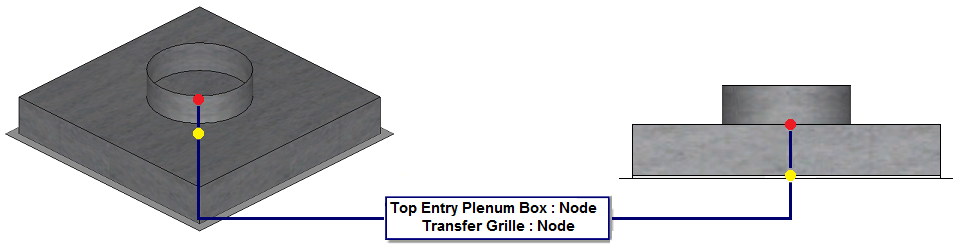
Note that each individual item has a distinctive node insertion point location, as shown below:

- Use Move, Rotate, and Snapping features to ensure that the Top Entry Plenum Box item (the blue node shown above) is positioned in the appropriate relationship with the Transfer Grille (the green node shown above).
- When the items are positioned in the desired location and orientation, at the command line, type SAVEASSUBASSEMBLY and then press Enter.
The Select Objects prompt displays.
- Select (click on) the two items that will be included in this sub assembly.
For this example, select the Transfer Grille item and the Top Entry Plenum Box item.
- When you have finished selecting the objects to be included in this sub assembly, press Enter to end the command.
The Save As dialog displays.
- Name and save this new item (sub assembly) to an appropriate location within the folder structure, and click Save.
- Next, edit and customise this new sub assembly item by typing FOLDERS.
- Locate the sub assembly item just saved, then right-click on it and select Edit.
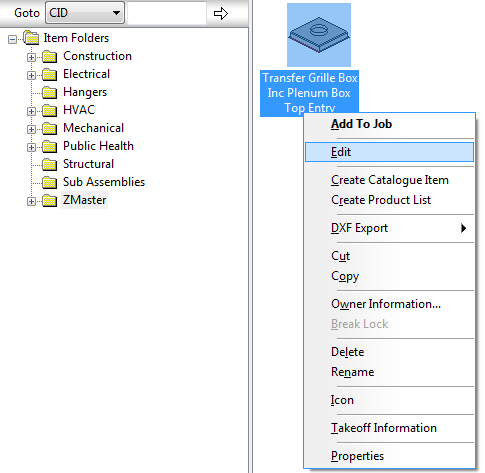
The Edit Sub Assembly dialog displays.
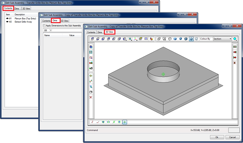
The Edit Sub Assembly dialog has three tabs: Contents, Dims, and 3D View. For more information, see Edit Sub Assembly Dialog.
The next steps are to customise and configure the important dimensions associated with the sub assembly so that it can function as a dynamically-sized individual item.
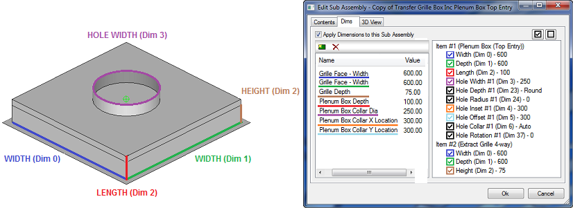
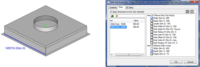
- Click the Dims tab and then enable (check) the Apply Dimensions to this Sub Assembly option, as shown below.
The dimensions for each item included in this sub assembly are listed on this tab, similar to what is shown below.
 Note: Prior to setting up these dimensions, make sure that you plan and understand the dynamics that will be required to create the sub assembly. In this example, the goal is to create a sub assembly that dynamically specifies the width of Item #1(Plenum Box Top Entry) with Item #2 (Transfer Grille).
 - Click New Dimension
 .
.
The default Dim #1 dimension is added, with a value that is not yet set.
- In the Name field, specify an appropriate name for this new dimension by typing over the default dimension name of Dim #1.
For example, name this dimension Grille Face - Width, as shown below.
- Enter a value of 600.00 in the Value cell to specify the value for this new dimension.
- Link (associate) the dimensions for "Width (Dim 0)" for "Item #1" and "Item #2" by selecting (placing a check mark in) each appropriate dimension, as shown below.
- Click New Dimension"
.
A default Dim #2 dimension is added, with a value that is not yet set.
- Name this dimension as required.
- Link (associate) the dimensions for width (Dim 1) for Item #1 and item #2 by selecting (placing a check mark in) each appropriate dimension, as shown below.
This indicates the two items within the sub assembly are now being driven by one common dimension for width titled "Grille Face - Width".

This indicates that the two items within the sub assembly are now being specified by one common dimension for width (Dim 0) titled "Grille Face - Width".
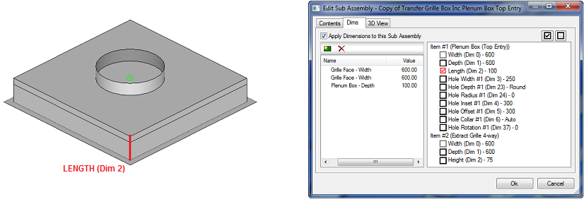
The next step is to dynamically specify the depth of item #1 (Plenum Box Top Entry) with Item #2 (Transfer Grille).
- Select "New Dimension"
.
The column below titled Name, will populate a "Dim#3" title,
- Name the new Dim #3 dimension as required (for example, Plenum Box Depth), then enter a value of 100.00 in the value column.
- Select the dimension for Length (Dim 2) by clicking (placing a check mark in) the box next to the dimension.
This indicates item #1 can independently specify the depth of the top entry plenum box.
- Click New Dimension
.
- Name the new Dim #4 dimension as required (for example, Grille Depth).
- Enter a value of 75.00 within the Value column.
- Select the dimension for Length (Dim 2) by placing a check mark in this field. This indicates item #2 specifies the depth of the grill.

The end result of creating this particular sub assembly is a fully configured dynamic sub assembly, where the user can dynamically specify the following dimensions:
- Grille Face Width: Item #1 (Plenum Box Top entry) & Item #2 (Transfer Grille)
- Grille Face Width: Item #1 (Plenum Box Top entry) & Item #2 (Transfer Grille)
- Grille Depth: Item #2 (Transfer Grille)
- Plenum Box Depth: Item #1 (Plenum Box Top entry)
- Collar X Location: Item #1 (Plenum Box Top entry)
- Collar Y Location: Item #1 (Plenum Box Top entry)