Assembly Constraints
Constrain geometry to position two or more components relative to each other, reduce degrees of freedom in the assembly, and create a Constraint Relationship between the involved components.
Design > Assemble > Constrain Components ![]()
To create a constraint, select faces, edges, or vertexes on two components, so they are flush, coincident, concentric, or at an angle. Then specify an offset distance or angle.
You can create multiple constraints at a time to build up a set.
Constraint Types
Align
An Align Constraint ![]() positions the components so that their selected geometry are flush, coincident, or concentric with each other.
positions the components so that their selected geometry are flush, coincident, or concentric with each other.
The orientation of the selected geometry is automatically determined by the combination of geometry types. For example, if you select two planes, they will become flush with each other. If you select a cylindrical face and a circular edge, they will be coincident with each other. Alignment types include:
- Coplanar: Positions selected geometry, so they are on the same plane.
- Coincident: Positions selected geometry, so they occupy the same space.
- Concentric: Positions selected geometry, so their center axis or center point are aligned.
Angle
An Angle Constraint ![]() positions the components so that their selected geometries are at a relative angle to each other.
positions the components so that their selected geometries are at a relative angle to each other.
When you create an Angle Constraint between two planar objects, it can solve in a few different ways. For a more predictable result, select a linear edge or sketch line to use as an axis for the Angle Reference.
Center
A Center Constraint positions one component between two faces of another component.
Your geometric selections determine how the components are positioned relative to one another:
- Select one face on Component 1 to center it between two faces on Component 2.
- Select two faces on Component 1 and two faces on Component 2 to align their midplanes.
- Select one face on Component 2 to center it between two faces on Component 1.
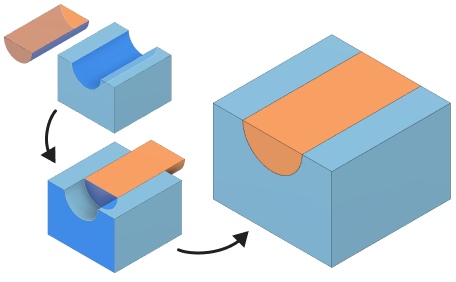
Tangent
A Tangent Constraint positions two components so one selection on the first component maintains tangency with geometry on a second component.
When you create a Tangent Constraint and select face geometry, you have the option to enable All Faces for the second component. If All Faces is enabled, then Component 1's selected face can transition across all faces of the Component 2’s selected body. If All Faces is unselected, then Component 1's selected face will maintain tangency to only Component 2's selected face.
Constraint Sets
A Constraint Set can contain different constraint types. In the dialog, each row in the table represents one constraint.
When you create a single constraint or a set of constraints, it displays in the Browser in the Relationships > Constraints folder.
If you create a Constraint Set, the individual constraint rows are nested under it.
- Individual Constraint
- Constraint Set
- Individual Constraint in a set
Default constrained position
To set the default position for new constraints in new designs, in the upper right corner open Preferences, then navigate to Design > Assemblies. Locate the Default constrained position setting and select a default:
- Click point: Moves the constrained components in the canvas to the cursor's click point on the selected geometry.
- Closest position: Moves the constrained components to the position closest to its starting position with the new constraint applied.
Offset Limits
Offset Limits let you define and specify a range that the component can move in the offset direction.
You can set limits for Angle and Align Constraint types. If there are multiple constraint rows in the table, select the constraint row you want to set limits for. To set limits for an angle constraint, you need to select an Angle Reference first.