Activity 1: Create components and add As-built Joints
In this activity, you perform the top-down design method and assemble components by:
Sketching a 2D profile for three components.
Using the Press Pull command to extrude the profile into components.
Grounding a component (larger box).
Applying As-built Joints to the smaller box and cylindrical component to fix their position and specify their motion.
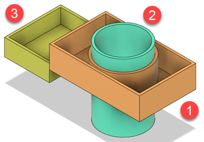
Larger box component (1), cylindrical component (2), smaller box component (3)
Prerequisites
- Ensure your units are set to mm instead of inches.
Steps
Start a sketch on the XZ (Top) plane.
If necessary, enter the Design workspace by clicking the workspace switcher and selecting Design.
If necessary, open a new design. To open a new design, click File > New Design.
Click Solid > Create > Create Sketch.
Select the XZ (Top) plane to sketch on.
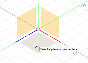
When you have selected the plane, you enter the Sketch contextual tab, which contains commonly used Sketch tools. The Sketch Palette is also available, which lists options relevant to your current task or the currently selected sketch entity.
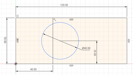
Create a 2D sketch of the three components. The circle sketch is not fully defined as we will move its position later.
Click Sketch > Create > Rectangle > 2-Point Rectangle.
Hover over the origin (or center) of the sketch. The cursor snaps automatically to this location.
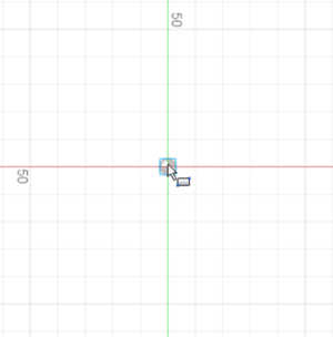
Click once to begin placing the first point of the rectangle.
Drag the mouse away to start sketching a rectangle and click again when it is 50 mm x 120 mm to complete sketching the rectangle.
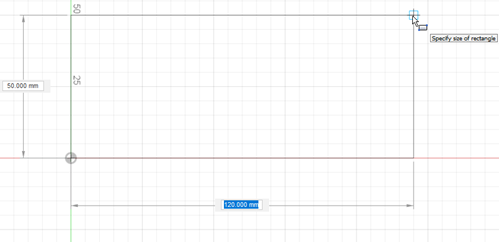
Click Sketch > Create > Line.
Sketch a vertical line that is 40 mm away from the left edge of the rectangle.
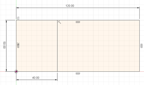
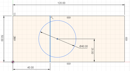
Sketch a circle close to the vertical line and ensure it is 25 mm from the bottom edge of the rectangle and 40 mm in diameter. The circle sketch is not fully defined as we will move its position later on in the tutorial. Click Finish Sketch.
Create the first component (larger box) so that it is 20 mm in height. Ensure you create a New Component and not a Body.
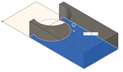
Click Solid > Modify > Press Pull.
Select the sketch profile on the right.
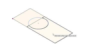
From the Operation list, select New Component.
Enter 20 mm for the Distance. Click OK
If the remainder of your sketch disappears, find the sketch folder in the Browser and click the
 icon to ensure that the sketch is visible.
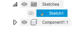
Create the cylinder component so it extends 30 mm on either side of the sketch. Ensure you create a New Component and not a Body.
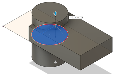
Click Solid > Modify > Press Pull.
Select the two sketch profiles that make the circle.
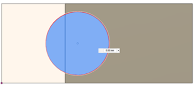
From the Direction list, select Symmetric.
From the Operation list, select New Component.
Enter 30 mm for the Distance. Click OK.
Now that there is more than a single component, click Inspect > Display Component Colors
 (
(Shift+F) to distinguish between different components in the canvas.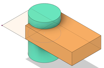 Note: The colors are assigned automatically. Do not worry if your color does not match what is shown in this tutorial. If you wish to. you can change the color coding.
Create the final component so that it extends 5 mm above the sketch and 10 mm below the sketch. Ensure you create a New Component and not a Body.
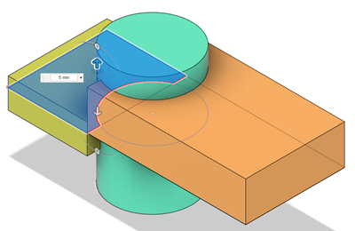
Click Solid > Modify > Press Pull.
Select the profile on the left.
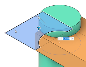
From the Direction list, select Two Sides.
From the Operation list, select New Component.
Under Side 1, Enter 5 mm for the Distance.
Under Side 2, Enter 10 mm for the Distance. Click OK.
Note: You now have three components in the browser.
Shell the components so that they have 2 mm thickness.
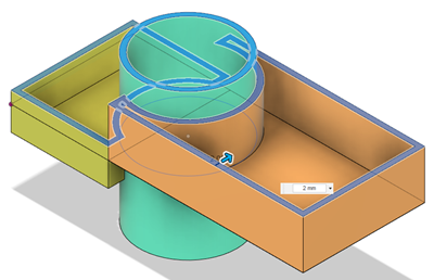
Click Solid > Modify > Shell.
Click the top face of each component.
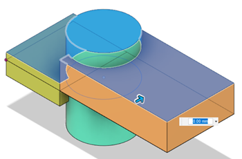
Enter 2 mm for Inside Thickness. Click OK.
Modify the sketch so that the cylindrical component is inside the larger box only (it is currently in between both the boxes).
In the Browser, right-click the sketch you created and click Edit Sketch. The 2D sketch appears.
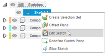
Click and drag the center point of the circle to the right so it is no longer overlapping both components.

In the Sketch Palette, click Finish Sketch. An updated version of the model appears because all three components were created from the same sketch, which is an example of the benefits of top-down design.
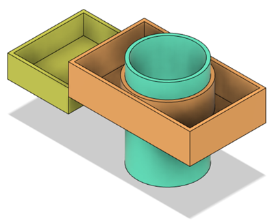
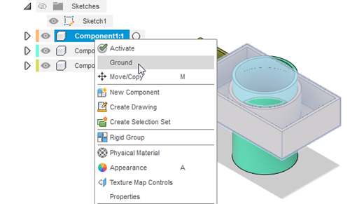
Ground the larger box component in space. In the Browser, right-click Component1:1 then click Ground. You can no longer move component 1 freely in space as it is now fixed.
 Note: Before you fix a component in space, ensure that no components have moved from their original position. If they have moved, a Revert button appears in the Position panel of the Ribbon to let you move them back into place. Click the Revert button
 if necessary.
Use a rigid As-built Joint to fix the position of the smaller box in relation to the larger box (which is grounded).
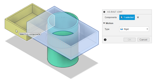
- Click Solid > Assemble > As-built Joint.
- From the Type list, select Rigid.
- Select the larger box component, then select the smaller box component. The rigid motion animation previews in the canvas. Click OK.
Tip: You can preview the joint-motion again by clicking
 next to Animate from the AS-BUILT JOINT dialog.
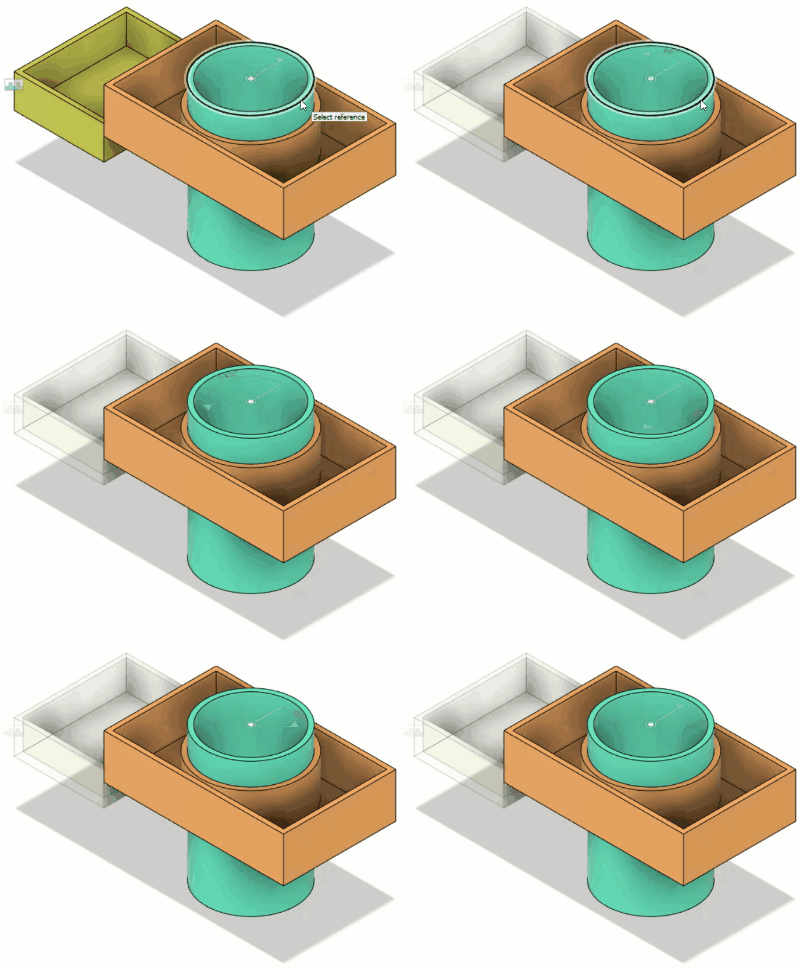
Use a revolute As-built Joint to fix the position of the cylinder.

Click Solid > Assemble > As-built Joint.
From the Type list, select Revolute.
Select the cylindrical component, then select the larger box component.
If necessary, click the button next to Position
 to ensure it is active.
Select the top-outer edge of the cylindrical component for the Position. The revolute motion animation previews in the canvas. Click OK.
Activity 1 summary
In this activity, you performed the top-down design method and assembled three components by:
- Sketching a 2D profile for three components.
- Using the Press Pull command to extrude the profile into components.
- Grounding a component (larger box).
- Applying As-built Joints to the smaller box and cylindrical component to fix their position and specify their motion.