Activity 2: Adding Joints and As-built Joints to components
In this activity, you assemble a camera stand that has been designed using the top-down method by:
Adding As-built Joints to components that are in the right position.
Adding Joints to components that are not in the right position.
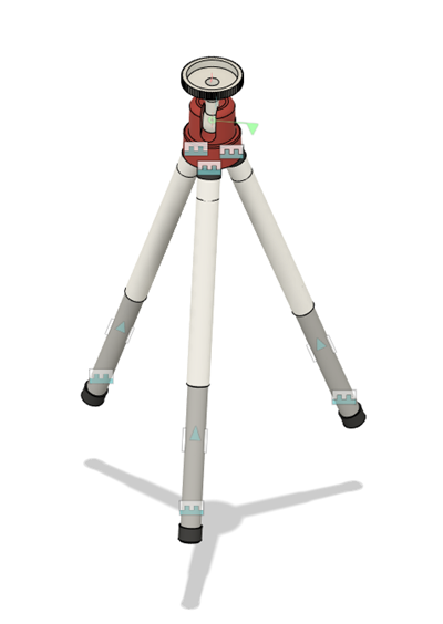
Multiple Joints and As-built Joints added to camera stand
Prerequisites
- Data file location: Basic Training > 06 - Assemblies > 06_tripod
Steps
Open the tripod data file in the canvas.
If the Data Panel is not currently shown, click Show Data Panel
 at the top of the screen.
In the Data Panel, scroll down until you reach Samples.
Double-click the Basic Training folder to open it.
Double-click the 06 - Assemblies folder to open it.
Click File > Save as and save a copy to your desired location so you can work on it.
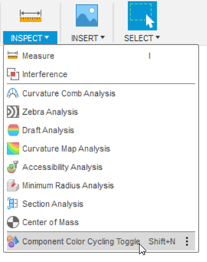
If your tripod does not appear as the color coding shown below, click Inspect > Display Component Colors
 (
(Shift+F).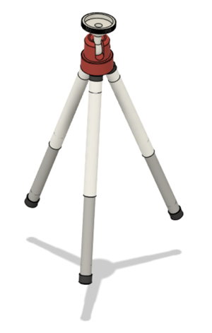
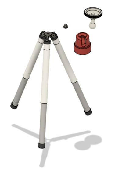
Click and drag the red fixture, the screw for the red fixture, and the white camera mount to the side and capture the new position.
Tip: If you accidentally move any other components out of place, a Revert button appears in the Position panel of the Ribbon to let you move the components back into place. Click the Revert button
 if necessary.
Click and drag the red fixture and move it to the side.
Click and drag the white camera mount and move it to the side.
Click and drag the fixture screw and move it to the side.
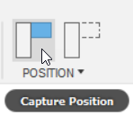
Click Capture Position to se the current position of all the components as their default position.
Ground the stand bracket. Grounding a component locks it in its current position. Typically, you ground at least one component in an assembly.
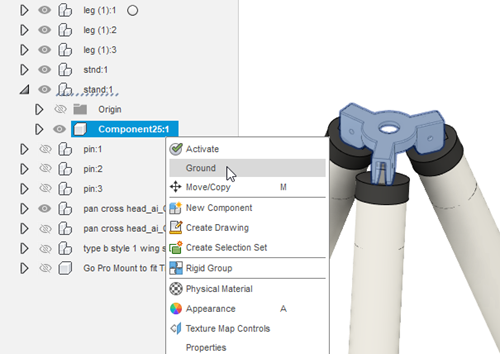
- In the Browser, expand stand:1.
- Right-click Component25:1 and click Ground.
Add a slider As-built Joint between the legs and their housing.
Click Solid > Assemble > As-built Joint. Make sure it is the As-built Joint command and not the Joint command.
From the Type list, select Slider.
Click the gray cylinder as the first component.
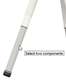
Click the white cylinder as the second component.
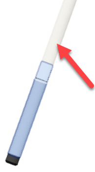
If necessary, click the button next to Position
 to ensure it is active.
Select the lower circular edge of the white cylinder for the Position. The slider motion animation previews in the canvas. Click OK.
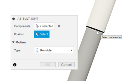
Note: The legs are three instances of the same subassembly. Applying a joint to one instance adds that joint to all three instances.
If necessary, click the Revert button
 to go back to the component arrangement that was there before you tested the slider motion.
Add a rigid As-built Joint between the bottom end cap and the gray cylinder legs.
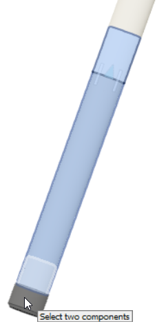
- Click Solid > Assemble > As-built Joint.
- From the Type list, select Rigid.
- Select one of the bottom end caps and the gray leg attached to it. The rigid motion animation previews in the canvas. Click OK.
Note: The end cap is also part of the leg subassembly. Applying a joint to one of the end caps applies a joint to all three end caps.
Add a rigid As-built Joint between the top end cap and the white cylinder.
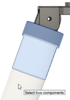
- Click Solid > Assemble > As-built Joint.
- From the Type list, select Rigid.
- Select one of the top end caps and the white cylinder attached to it. The rigid motion animation previews in the canvas. Click OK.
Add a rigid As-built Joint between the top end cap and the connector. The connector is a tombstone shaped component that connects the legs to the stand bracket.
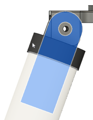
- Click Solid > Assemble > As-built Joint.
- From the Type list, select Rigid.
- Select one of the top end caps and the tombstone connector attached to it. The rigid motion animation previews in the canvas. Click OK.
Add a revolute As-built Joint between the connector and the stand bracket.
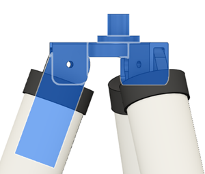
Click Solid > Assemble > As-built Joint.
From the Type list, select Revolute.
Select one of tombstone connectors and the bracket as the components.
If necessary, click the button next to Position
 to ensure it is active.
Mouse over the outer edge of the hole in the stand bracket and hold down the CTRL key. Holding the CTRL key keeps the glyph
 on-screen so you can select it.
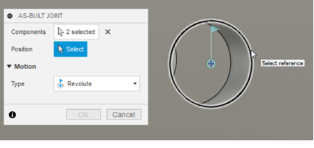
While continuing to hold down the CTRL key, click the glyph to select it as the position where the connector should rotate around. The revolute motion animation previews in the canvas. Click OK.
Note: This is a joint between one of the leg subassemblies and a component in the main assembly, so it is applied to the selected subassembly only. Next, we repeat this process to join the other two legs.
- Repeat steps a to f for the other two legs.
Tip: Remember, if at any point you move the components accidentally and want to revert to their original position, click the Revert button
 . It will not remove any motion you have already added.
Add a rigid joint between the screw and the stand bracket.
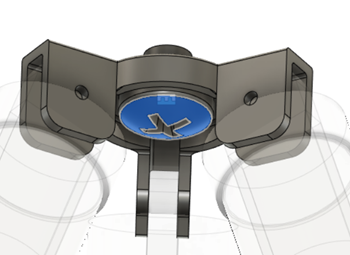
Click Solid > Assemble > Joint. Make sure you use the Joint command and not the As-built Joint we have been using.
From the Type list, select Rigid.
Select the flat face on the underside of the screw cap as the first component.
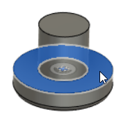
Select the bottom edge of the hole in the stand bracket as the second component. Click OK.
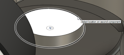
Add a rigid Joint between the red fixture and the stand bracket.
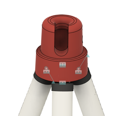
- Click Solid > Assemble > Joint.
- From the Type list, select Rigid.
- Mouse over the bottom face of the red fixture and click the glyph at the center of the face as the first component.
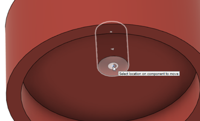
- Mouse over the flat face of the stand bracket then hold down the CTRL key. Holding down the CTRL key lets you snap onto locations that are displayed.
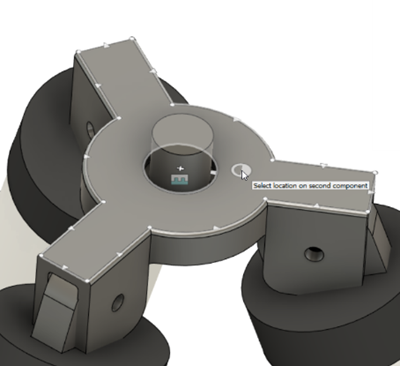
- While holding the CTRL key, move the cursor to the center of the hole and click to select the glyph at the center as the second component. The rigid motion animation previews in the canvas. Click OK.
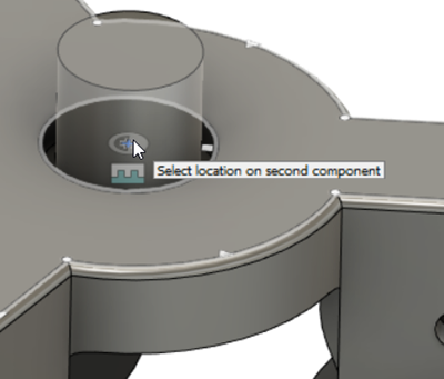
Add a ball joint between the red fixture and the camera mount.
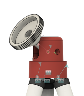
Click Solid > Assemble > Joint.
From the Type list, select Ball.
Select the ball on the bottom of the camera mount as the first component.
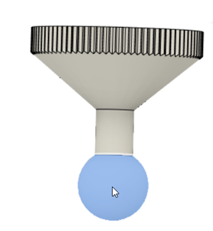
Select the ball cavity inside the red fixture as the second component. The ball motion animation previews in the canvas. Click OK.
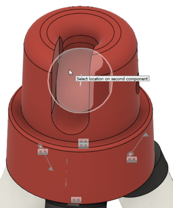
Note: Fusion does not detect material interference unless you set up contact sets.
Test the slider movement on the stand legs, the revolution movement between the legs and the bracket, and the ball movement on the mount.
Test the slider motion. Double click the slider icon on between the two cylinders of the stand.
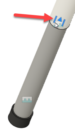
An arrow appears. Drag the arrow up and down along the cylinder to test its movement.
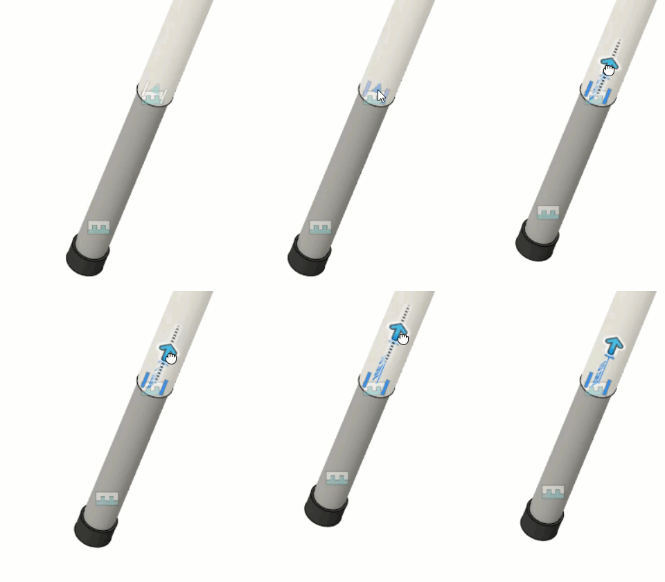
Tip: You can also click and slide the gray cylinder in and out of the white cylinder in the canvas.
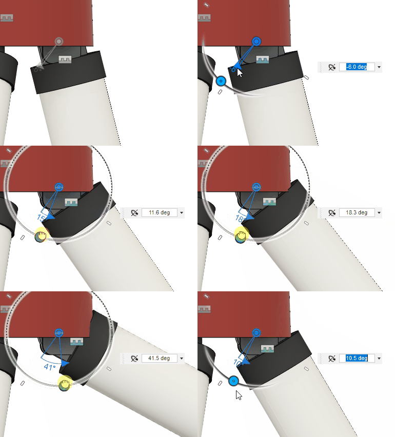
Test the revolute motion. Double click a revolute joint icon on one of the legs.
Use the manipulator on the canvas to rotate the leg about the bracket.
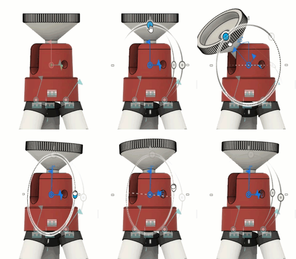
Test the ball motion. Double click the revolute joint icon on the red fixture.
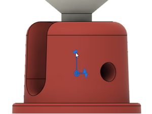
Use the manipulator on the canvas to rotate the camera mount within its cavity.
Activity 2 summary
In this activity, you assembled a camera stand that was designed using the Top-down method by:
- Adding As-built Joints (rigid, revolute, and slider) to components that were in the correct position.
- Adding Joints (rigid and ball) to components that were not in the right position.