Generate a 2D Adaptive Clearing toolpath
On the Manufacture workspace toolbar, click Milling > 2D > 2D Adaptive Clearing.
The 2D Adaptive dialog opens.
On the Tool tab, click Select to pick a tool. If you have not created a tool to use, in the left panel of the dialog, from the Fusion Library, pick a tool from the Sample Tools library.
Tip: Bull-nosed and flat end mills are best suited for removing material with a toolpath like Adaptive Clearing.On the Geometry tab, with Pocket Selections active, select solid faces, edges, or sketches as the machining area.
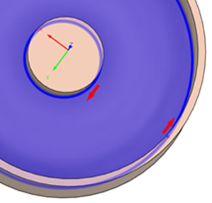
Tip: Mouse over the Pocket Selections box more information.If you've selected an edge or a sketch, verify that the red contour arrows are pointing in the correct direction. For internal pockets, the contour arrow should point counterclockwise. For bosses, the contour arrow should point clockwise. If necessary, click the contour arrow to flip its direction.
On the Passes tab, adjust the Optimal Load value to increase or decrease how much material the tool is engaged with at any given time.
Tip: Consult your tooling supplier for stepover recommendations. Typically this value might be between 10% and 40% of the tool diameter, depending on the material type, tool size and rigidity of the setup.Optional steps:
To machine at multiple depths, enable the Multiple Depths group and specify the Maximum Roughing Stepdown. This will create passes that may vary in depth: the toolpath starts with equal stepdowns up to the maximum value, but the final pass may be smaller depending on the remaining material.
To make multiple depths in equal distances between machining passes, select Use Even Stepdowns. The total cutting depth will be divided into even stepdowns, ensuring none exceed the Maximum Roughing Stepdown value. This helps maintain consistent cutting conditions and prolong tool life.
To adjust the material for a future finishing operations, enable the Stock to Leave checkbox.
To reduce the NC program size, enable Smoothing.
To adjust the final Z depth, go to the Heights tab and offset the Bottom Height. The Model Bottom is the default final depth.
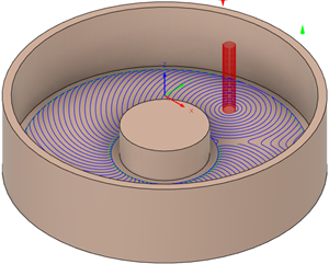
Click OK.
The toolpath is generated.