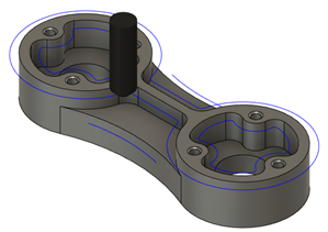
Generate a 2D Chamfer toolpath
On the Manufacture workspace toolbar, click Milling > 2D > 2D Chamfer.
The 2D Chamfer dialog opens.
On the Tool tab, click Select to pick a tool. If you have not created a tool to use, in the left panel of the dialog, from the Fusion Library, pick a tool from the Sample Tools library.
Tip: Engrave/Chamfer mills are best suited for removing material with a 2D Chamfer toolpath.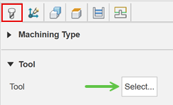
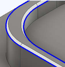
On the Geometry tab, with Contour Selection active, select edges or sketches to drive the tool.
If the chamfers are modeled on a part, select the lower edge as the contour selection. If there are no chamfers modeled, then select the sharp edge.
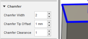
If the chamfer is not modeled, on the Passes tab:
Specify the Chamfer Width.
(Optional) To avoid nearby walls, enter a Chamfer Clearance distance.
If the chamfer is modeled, on the Passes tab:
Set the Chamfer width to 0.
Set the Chamfer Clearance to 0.
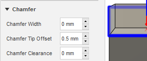
Specify a Chamfer Tip Offset to adjust the position of the tool relative to the chamfer so that you are not cutting with near the tip of the tool. For modeled chamfers, you may also need to adjust the offset so that the flute of the tool covers the entire chamfer.
Optional steps:
To ensure that material is cleared at the entry point of the tool, enter a Finishing Overlap distance.
To reduce the NC program size, select the Smoothing checkbox.
To manually specify the order in which the chamfers are machined, select the Preserve Order checkbox.
For smoother machine motion when cutting chamfers, from the Outer Corner Mode drop-down list, select Roll around corner. The resulting geometry of the chamfer is the same, independant of the Outer Corner Mode option used.
Click OK.
The toolpath is generated.