Probe WCS reference
Probing cycles are a machine process to establish a zero point on a part and they can also be used to do part inspection.
Manufacture > Inspection > Probing > Probe WCS ![]()
You can probe the part model or the stock body. By selecting the geometric feature or point to be probed, the appropriate probing cycle is selected and the available options are updated.
Probing cycles can be used to find various positions:
- Single axis probing
- Corner probing
- Block center probing
- Rectangular cavity center probing
- Circular boss center probing
- Circular hole center probing
- Rectangular and Circular cavity with Islands
- Between 2 walls/faces
Specify tolerances to verify that the position and size of geometric features on the stock, or the part model, are in tolerance. For example, to check that the correct stock or part is being used and that it has been loaded correctly. Instruct the CNC machine to stop machining and display a message on the controller if the positions or size are out of tolerance.
The Probe dialog contains four tabs: Tool, Geometry, Heights, and Settings. These tabs contain many of the same parameters you might find for any machining toolpath.
Tool
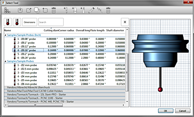
Click Select and scroll down to the Samples/Sample Probes library to select a probe, and then click OK.
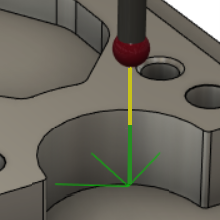
Link Feedrate
Defines the speed of the probe during link moves, which are performed before and after the probe leads in and then touches the part. Link moves are displayed in yellow on the canvas.
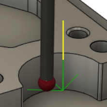
Lead-In Feedrate
Defines the speed of the probe during lead moves, which are performed before and after the probe touches the part. Lead moves are displayed in green on the canvas.
If the probe is set up to perform two touches, the first touch is at the Lead-In Feedrate and then the second touch is at the Measure Feedrate.
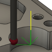
Measure Feedrate
Defines the speed of the probe during measure moves, which is when the probe touches the part.
If the probe is set up to perform two touches, the first touch is at the Lead-In Feedrate and then the second touch is at the Measure Feedrate.
Probe Mode
Lets you choose between selecting faces from the part Model or the Stock. Selection options change based on your choice.
Selecting one wall creates a single axis probing function. Selecting the top face may provide additional probing options. The faces you select determine the type of probing cycle you can perform. Keep in mind, you do not have to be on the Geometry tab to select a face.
Probe Surface(s) - Model
Reports the number of selected Faces from the model. Your selection determines the type of probing to be performed.
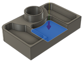
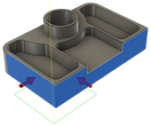
Examples of selected faces and Probe Type options:
 |
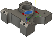 |
| Single surfaces (Z Surface shown) | Single surfaces at an angle (Angle Along Y-Axis shown) |
 |
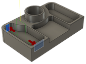 |
| Corners (XY Outer shown) | Channels (Y-Channel shown) |
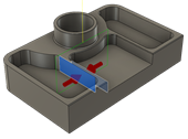 |
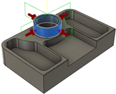 |
| Walls (X Wall shown) | Bosses (XY Circular Boss shown) |
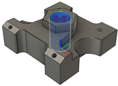 |
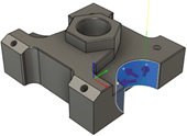 |
| Holes (XY Circular Hole shown) | Partial holes and bosses (XY Circular Partial Hole shown) |
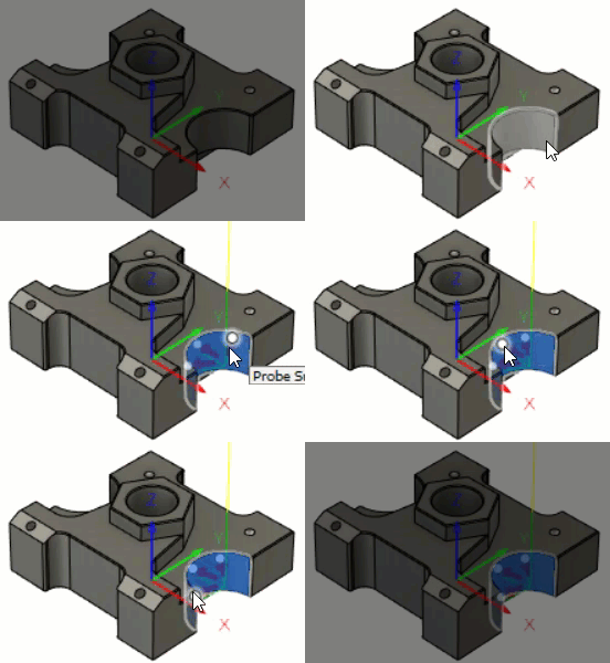
Example of changing the position of points on a partial hole.
If you want to probe at the exact point that you clicked on the model, select Use Selection Point.
Probe Stock Surface(s) - Stock
Reports the number of selected Faces from the stock. Your selection determines the type of probing to be performed.
Examples of selected faces and Probe Type options:
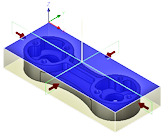 |
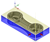 |
| Top face selected for stock center (XY Rectangular Boss shown) | Two perpendicular walls selected for stock corner (XY Outer Corner shown) |
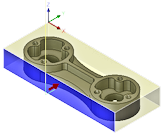 |
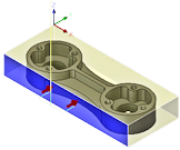 |
| X or Y single wall selected (Y Surface shown) | X or Y single wall selected (Angle Along Y-Axis shown) |
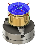 |
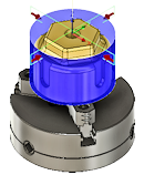 |
| Top face selected for boss center (XY Circular Boss shown) | Cylindrical face selection for boss center (XY Circular Boss shown) |
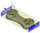 |
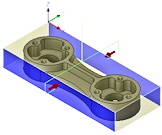 |
| Two opposite walls in X for X block center (X-Wall shown) | Two opposite walls in Y for Y block center (Y-Wall shown) |
Use Selection Point
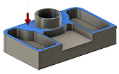
When selected, forces probing at the actual point picked on the selected surface. A red arrow shows the selected point.
Probe Type
Shows the available probing cycles based on your selection. The Probe Mode and the face selection determines the type of probing that can be performed.
Approach
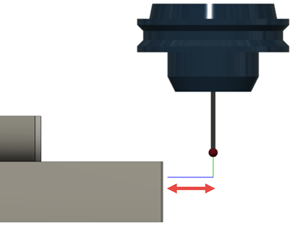
Enter a value to specify the distance from the surface normal where the probe starts to approach the surface. By default, Approach is twice the probe diameter.
Spacing
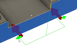
Sets the probe spacing between points when an angle is being calculated from the selected face.
Overtravel
Enter a value to specify the maximum distance the probe can move beyond the expected contact point and still record a measurement.
If no contact is made within this distance, the probe returns an invalid measurement.
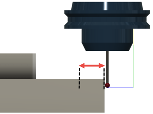
Tolerances
The acceptable value of deviation in Position, Size, or Angle of the measured geometric feature on the model or stock. These bilateral tolerances are the amount that the position, size, or angle can vary from their nominals and still be considered in tolerance.
For example, when probing the diameter of a boss feature, the size tolerance can be thought of as the minimum and maximum diameter band around the actual diameter. A tolerance of 0.1 mm for a 15 mm diameter boss means that the diameter must be between 14.9 and 15.1 mm.
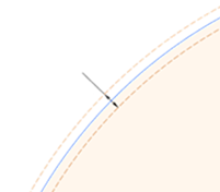
If the measured geometric feature is out of tolerance, you can use the Out of Position, Wrong Size, and Askew options on the Action tab to instruct the CNC machine to stop machining and display a message on the controller.
Heights
The different heights for the probe.
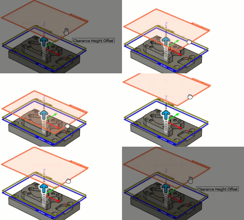
Clearance Height
The first height the tool moves to on its way to the start of probing and the point it returns to after the process is finished. This position can be defined in reference to the stock, the model, another reference, or a user-selected position. The height is shown in orange.
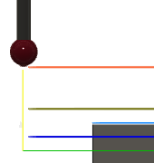
From defines the reference for the Clearance Height:
- Retract height: Incremental offset from the Retract Height.
- Bottom height: Incremental offset from the Bottom Height.
- Model top: Incremental offset from the Model Top.
- Model bottom: Incremental offset from the Model Bottom.
- Stock top: Incremental offset from the Stock Top.
- Stock bottom: Incremental offset from the Stock Bottom.
- Selection: Incremental offset from a Point (vertex), Edge, or Face selected on the model.
- Probing surface top: Incremental offset from the top of the lowest selected surface.
- Origin (absolute): Absolute offset from the Origin that is defined in either the Setup or in Tool Orientation within the specific operation.
Offset is a shift relative to the From selection. Enter a value, or drag the orange ring on the canvas.
Retract Height
Sets an intermediate height between the Clearance Height and the Bottom Height positions, used between probing moves. If the probing cycle needs to probe several locations, this is the height the probe moves to between probing. The height is shown in dark green.
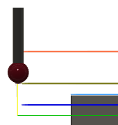
From defines the reference for the Retract Height:
- Clearance height: Incremental offset from the Clearance Height.
- Bottom height: Incremental offset from the Bottom Height.
- Model top: Incremental offset from the Model Top.
- Model bottom: Incremental offset from the Model Bottom.
- Stock top: Incremental offset from the Stock Top.
- Stock bottom: Incremental offset from the Stock Bottom.
- Selection: Incremental offset from a Point (vertex), Edge, or Face selected on the model.
- Probing surface top: Incremental offset from the top of the lowest selected surface.
- Origin (absolute): Absolute offset from the Origin that is defined in either the Setup or in Tool Orientation within the specific operation.
Offset is a shift relative to the From selection. Enter a value, or drag the dark green ring on the canvas.
Bottom Height
Determines the true probing depth. This position is to the contact point of the probe, not the bottom of the probe tip. By default, a spherical (ball) type of probe is offset up by its radius. The height is shown in blue.
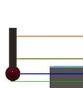
From defines the reference for the Bottom Height:
- Clearance height: Incremental offset from the Clearance Height.
- Retract height: Incremental offset from the Retract Height.
- Model top: Incremental offset from the Model Top.
- Model bottom: Incremental offset from the Model Bottom.
- Stock top: Incremental offset from the Stock Top.
- Stock bottom: Incremental offset from the Stock Bottom.
- Selection: Incremental offset from a Point (vertex), Edge, or Face selected on the model.
- Probing surface top: Incremental offset from the top of the lowest selected surface.
- Origin (absolute): Absolute offset from the Origin that is defined in either the Setup or in Tool Orientation within the specific operation.
Offset is a shift relative to the From selection. Enter a value, or drag the blue ring on the canvas.
WCS
Controls which coordinate system drives this probing operation.
Override Driving WCS
When selected, the probe is driven from a different coordinate system (WCS Override) to that defined in the setup (WCS Offset).
The WCS Override for this probing operation is not updated, but the WCS Offset for subsequent machining operations is updated. This locks the coordinate system for the probe.
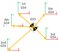
Example of updated WCS Offset (1=G54), but unchanged WCS Override (2=G55), for multiple parts.
When deselected, the probe is driven from the same coordinate system as that defined in the setup (WCS Offset).
The WCS Offset for this probing operation and subsequent machining operations is updated.
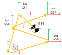
Example of updated WCS Offset (1=G54) for multiple parts.
WCS Override
The number of the coordinate system that drives this probing operation. The number matches a specific G-code, which is defined by the post processor.
WCS To Be Updated
The number of the coordinate system in the setup (WCS Offset), which will be updated based on the results of this probing operation. The number matches a specific G-code, which is defined by the post processor.
Out of Position
When selected, instructs the CNC machine to stop machining and display a message on the controller when the position of the geometric feature is out of tolerance.
Wrong Size
When selected, instructs the CNC machine to stop machining and display a message on the controller when the size of the geometric feature is out of tolerance.
Askew
When selected, instructs the CNC machine to stop machining and display a message on the controller when the angle of the geometric feature is out of tolerance.
Print Results
When selected, displays the results from probing on the CNC machine's controller. The results can also be output to a machine-generated results file, which can be imported into Fusion.
By default, results are separated using an incremental numbering system. The feature number is incremented but the part number is not. This is useful when probing multiple faces on a single part.
Select Increment Component to increment the part number in the results, while resetting the feature number. This is useful when probing the same face on multiple parts.