Engrave reference
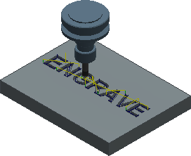
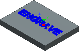
Engrave machines along the contours with V-shaped chamfer tools. Select the profile with Edges, Sketches or Faces. The tip of the tool is used to create sharp edges on the cavity corners.
Manufacture > Milling > 2D > Engrave ![]()
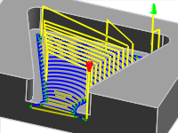
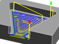
 Toolpath generated for the selected Edges |
 The Edge is selected (Blue). The area is cleared out. The corners are sharpened with the tool. |
 Tool tab settings
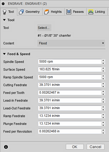
Coolant
Select the type of coolant used with the machine tool. Not all types will work with all machine postprocessors.
Feed & Speed
Spindle and Feedrate cutting parameters.
- Spindle Speed - The rotational speed of the spindle expressed in Rotations Per Minute (RPM)
- Surface Speed - The speed which the material moves past the cutting edge of the tool (SFM or m/min)
- Ramp Spindle Speed - The rotational speed of the spindle when performing ramp movements
- Cutting Feedrate - Feedrate used in regular cutting moves. Expressed as Inches/Min (IPM) or MM/Min
- Feed per Tooth - The cutting feedrate expressed as the feed per tooth (FPT)
- Lead-In Feedrate - Feed used when leading in to a cutting move.
- Lead-Out Feedrate - Feed used when leading out from a cutting move
- Ramp Feedrate - Feed used when doing helical ramps into stock
- Plunge Feedrate - Feed used when plunging into stock
- Feed per Revolution - The plunge feedrate expressed as the feed per revolution
 Geometry tab settings
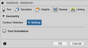
Contour Selections
Select the profile to be engraved using Edges, Sketches or Faces. Contiguous geometry is automatically chained. Engrave finds the center and drives the chamfer tool between the selected edges. The tool moves up and down as the width of the area being cut changes. Text and imported art work is commonly machined using Engrave,
Tool Orientation
Specifies how the tool orientation is determined using a combination of triad orientation and origin options.
The Orientation drop-down menu provides the following options to set the orientation of the X, Y, and Z triad axes:
- Setup WCS orientation - Uses the workpiece coordinate system (WCS) of the current setup for the tool orientation.
- Model orientation - Uses the coordinate system (WCS) of the current part for the tool orientation.
- Select Z axis/plane & X axis - Select a face or an edge to define the Z axis and another face or edge to define the X axis. Both the Z and X axes can be flipped 180 degrees.
- Select Z axis/plane & Y axis - Select a face or an edge to define the Z axis and another face or edge to define the Y axis. Both the Z and Y axes can be flipped 180 degrees.
- Select X & Y axes - Select a face or an edge to define the X axis and another face or edge to define the Y axis. Both the X and Y axes can be flipped 180 degrees.
- Select coordinate system - Sets a specific tool orientation for this operation from an Inventor User Coordinate System (UCS) in the model. This uses both the origin and orientation of the existing coordinate system. Use this if your model does not contain a suitable point & plane for your operation.
The Origin drop-down menu offers the following options for locating the triad origin:
- Setup WCS origin - Uses the workpiece coordinate system (WCS) origin of the current setup for the tool origin.
- Model origin - Uses the coordinate system (WCS) origin of the current part for the tool origin.
- Selected point - Select a vertex or an edge for the triad origin.
- Stock box point - Select a point on the stock bounding box for the triad origin.
- Model box point - Select a point on the model bounding box for the triad origin.
 Heights tab settings
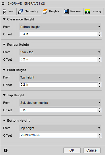
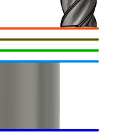
Clearance Height
The Clearance height is the first height the tool rapids to on its way to the start of the tool path.
Clearance Height
- Retract height: incremental offset from the Retract Height.
- Feed height: incremental offset from the Feed Height.
- Top height: incremental offset from the Top Height.
- Bottom height: incremental offset from the Bottom Height.
- Model top: incremental offset from the Model Top.
- Model bottom: incremental offset from the Model Bottom.
- Stock top: incremental offset from the Stock Top.
- Stock bottom: incremental offset from the Stock Bottom.
- Selected contour(s): incremental offset from a Contour selected on the model.
- Selection: incremental offset from a Point (vertex), Edge or Face selected on the model.
- Origin (absolute): absolute offset from the Origin that is defined in either the Setup or in Tool Orientation within the specific operation.
Clearance height offset
The Clearance height offset is applied and is relative to the Clearance height selection in the above drop-down list.
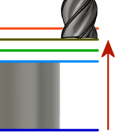
Retract Height
Retract height sets the height that the tool moves up to before the next cutting pass. Retract height should be set above the Feed height and Top. Retract height is used together with the subsequent offset to establish the height.
Retract Height
- Clearance height: incremental offset from the Clearance Height.
- Feed height: incremental offset from the Feed Height.
- Top height: incremental offset from the Top Height.
- Bottom height: incremental offset from the Bottom Height.
- Model top: incremental offset from the Model Top.
- Model bottom: incremental offset from the Model Bottom.
- Stock top: incremental offset from the Stock Top.
- Stock bottom: incremental offset from the Stock Bottom.
- Selected contour(s): incremental offset from a Contour selected on the model.
- Selection: incremental offset from a Point (vertex), Edge or Face selected on the model.
- Origin (absolute): absolute offset from the Origin that is defined in either the Setup or in Tool Orientation within the specific operation.
Retract height offset
Retract height offset is applied and is relative to the Retract height selection in the above drop-down list.
Feed Height
Feed height sets the height that the tool rapids to before changing to the feed/plunge rate to enter the part. Feed height should be set above the Top. A drilling operation uses this height as the initial feed height and the retract peck height. Feed height is used together with the subsequent offset to establish the height.
Feed Height
- Clearance height: incremental offset from the Clearance Height.
- Retract height: incremental offset from the Retract Height.
- Disabled: Disabling the Feed Height causes the tool to rapid down to the lead-in.
- Top height: incremental offset from the Top Height.
- Bottom height: incremental offset from the Bottom Height.
- Model top: incremental offset from the Model Top.
- Model bottom: incremental offset from the Model Bottom.
- Stock top: incremental offset from the Stock Top.
- Stock bottom: incremental offset from the Stock Bottom.
- Selected contour(s): incremental offset from a Contour selected on the model.
- Selection: incremental offset from a Point (vertex), Edge or Face selected on the model.
- Origin (absolute): absolute offset from the Origin that is defined in either the Setup or in Tool Orientation within the specific operation.
Feed height offset
Feed height offset is applied and is relative to the Feed height selection in the above drop-down list.
Top Height
Top height sets the height that describes the top of the cut. Top height should be set above the Bottom. Top height is used together with the subsequent offset to establish the height.
Top Height
- Clearance height: incremental offset from the Clearance Height.
- Retract height: incremental offset from the Retract Height.
- Feed height: incremental offset from the Feed Height.
- Bottom height: incremental offset from the Bottom Height.
- Model top: incremental offset from the Model Top.
- Model bottom: incremental offset from the Model Bottom.
- Stock top: incremental offset from the Stock Top.
- Stock bottom: incremental offset from the Stock Bottom.
- Selected contour(s): incremental offset from a Contour selected on the model.
- Selection: incremental offset from a Point (vertex), Edge or Face selected on the model.
- Origin (absolute): absolute offset from the Origin that is defined in either the Setup or in Tool Orientation within the specific operation.
Top offset
Top offset is applied and is relative to the Top height selection in the above drop-down list.
Bottom Height
Bottom height determines the final machining height/depth and the lowest depth that the tool descends into the stock. Bottom height needs to be set below the Top. Bottom height is used together with the subsequent offset to establish the height.
Bottom Height
- Clearance height: incremental offset from the Clearance Height.
- Retract height: incremental offset from the Retract Height.
- Feed height: incremental offset from the Feed Height.
- Top height: incremental offset from the Top Height.
- Model top: incremental offset from the Model Top.
- Model bottom: incremental offset from the Model Bottom.
- Stock top: incremental offset from the Stock Top.
- Stock bottom: incremental offset from the Stock Bottom.
- Selected contour(s): incremental offset from a Contour selected on the model.
- Selection: incremental offset from a Point (vertex), Edge or Face selected on the model.
- Origin (absolute): absolute offset from the Origin that is defined in either the Setup or in Tool Orientation within the specific operation.
Bottom offset
Bottom offset is applied and is relative to the Bottom height selection in the above drop-down list.
 Passes tab settings
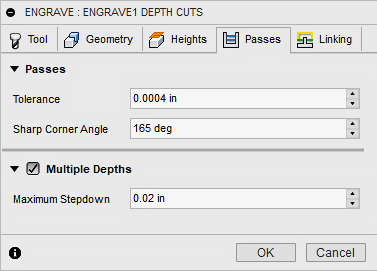
Tolerance
The tolerance used when linearizing geometry such as splines and ellipses. The tolerance is taken as the maximum chord distance.
 |
 |
| Loose Tolerance .100 | Tight Tolerance .001 |
CNC machine contouring motion is controlled using line G1 and arc G2 G3 commands. To accommodate this, Fusion approximates spline and surface toolpaths by linearizing them; creating many short line segments to approximate the desired shape. How accurately the toolpath matches the desired shape depends largely on the number of lines used. More lines result in a toolpath that more closely approximates the nominal shape of the spline or surface.
Data Starving
It is tempting to always use very tight tolerances, but there are trade-offs including longer toolpath calculation times, large G-code files, and very short line moves. The first two are not much of a problem because Fusion calculates very quickly and most modern controls have at least 1MB of RAM. However, short line moves, coupled with high feedrates, may result in a phenomenon known as data starving.
Data starving occurs when the control becomes so overwhelmed with data that it cannot keep up. CNC controls can only process a finite number of lines of code (blocks) per second. That can be as few as 40 blocks/second on older machines and 1,000 blocks/second or more on a newer machine like the Haas Automation control. Short line moves and high feedrates can force the processing rate beyond what the control can handle. When that happens, the machine must pause after each move and wait for the next servo command from the control.
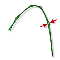
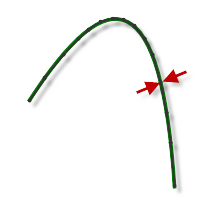
Sharp Corner Angle
The purpose of Engrave is to create sharp corners in the pocket by moving the cutter along the corner intersection. If the angle between edges is greater than this value, there will not be a corner clean out move.
 |
|
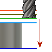
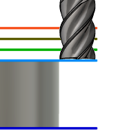
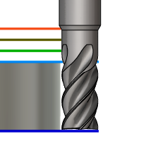
Multiple Depths
When enabled you can specify the Maximum Stepdown per cut.
 |
 |
|
| Disabled 1 Cut |
Enabled Max. Stepdown .020 in |
 Linking tab settings
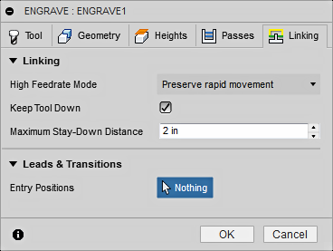
High Feedrate Mode
Specifies when rapid movements should be output as true rapids (G0) and when they should be output as high feedrate movements (G1).
- Preserve rapid movement - All rapid movements are preserved.
- Preserve axial and radial rapid movement - Rapid movements moving only horizontally (radial) or vertically (axial) are output as true rapids.
- Preserve axial rapid movement - Only rapid movements moving vertically.
- Preserve radial rapid movement - Only rapid movements moving horizontally.
- Preserve single axis rapid movement - Only rapid movements moving in one axis only (X, Y or Z).
- Always use high feed - Outputs rapid movements as (high feed moves) G01 moves instead of rapid movements (G0).
This parameter is usually set to avoid collisions at rapids on machines which perform "dog-leg" movements at rapid.
High Feedrate
The feedrate to use for rapid movements output as G1 instead of G0.
Keep Tool Down
When enabled, the strategy avoids retracting when the distance to the next area is below the specified stay-down distance.
Maximum Stay-Down Distance
Specifies the maximum distance allowed for stay-down moves.
 1" Maximum stay-down |
 2" Maximum stay-down distance |
Entry Positions
Select geometry near the location where you want the tool to enter.