Activity 1: Using adaptive clearing
In this activity, you orient the part with a 3+2 machining setup and use an adaptive clearing strategy to create the elliptical shaped feature.
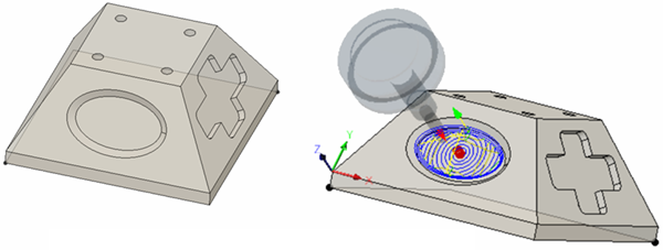
Before machining the part (left), after using adaptive clearing (right).
Prerequisites
- Ensure the Tutorial3 model is open.
- Ensure the Workspace is Manufacture.
Steps
On the Manufacture toolbar, Milling tab, select 3D > Adaptive Clearing
 .
.In the Adaptive Clearing dialog, set the tool to #12 – Ø8 R1 mm bullnose.
Select
 , Tool tab , on the Adaptive dialog, if not already selected.
Click the Select button.
In the Select Tool dialog, in the left panel, scroll to the bottom and select Tutorial Tools (Metric).
In the list of tools, click the tool #12 – Ø8 R1 mm (Bull nose end mill).
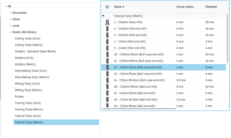
The Tutorial Tools (Metric) library is selected, then the specific tool is selected.
Click Select to select the tool and close the Select Tool dialog.
Define the orientation and the elliptical geometry to machine.
- On the Adaptive dialog, select
 , Multi-Axis tab.
 - Check the Tool Orientation box, to expand this group.
- Choose Select Z axis/plane & X axis from the Orientation drop-down menu.
- Ensure the Z Axis button is active and select the face containing the Ellipse, to define a face defining the Z-axis.
- Ensure the X Axis button is active and select the longest edge of the face you just selected. This selection defines the X direction.
- Choose Selected point from the Origin drop-down menu.
- Click the Point button for the Tool Orientation Origin parameter.
- Click the bottom left corner of the trapezoidal plane the ellipse is in to define the new origin.
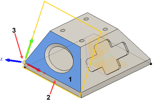
Plane defining the z axis direction (1), edge defining the direction of the X axis (2), corner defining the origin (3).
- On the Adaptive dialog, select
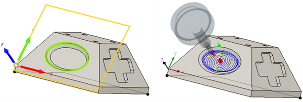
Pick the outer elliptical edge as the machining boundary.
Choose Selection in the Machining boundary perimeter.
Ensure the Machining boundary selection is active.
Click on the outer elliptical edge.
Select Tool center on boundary from the Tool Containment drop-down.
Click OK on the Adaptive dialog to start calculating the tool path.
Activity 1 summary
In this activity, you used a 3+2 machining technique to orient the part so the plane containing the ellipse is normal to the machine’s Z-axis. Then, you used adaptive clearing to rough cut the elliptical pocket.
Before machining the part (left), after using adaptive clearing (right).