Activity 6: Finish the outside of the part
In this activity, you finish the outside of the part with a 2D Contour operation.

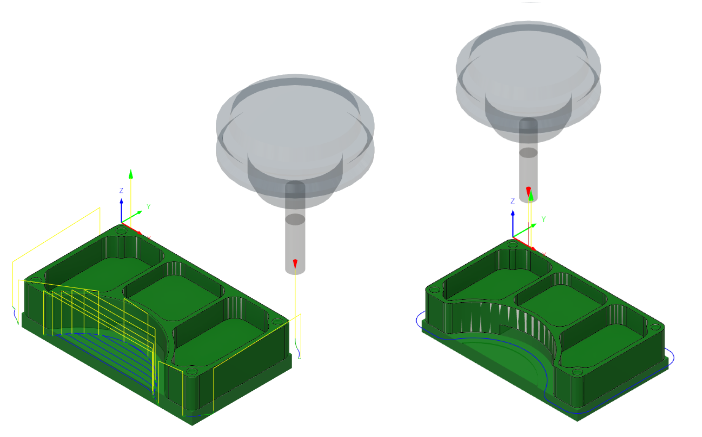
Before, showing the 2D Adaptive Clearing toolpath applied around the outside of the part (left). After, showing the 2D Contour toolpath applied around the outside of the part (right).
Prerequisites
- Activity 5 is complete.
Steps
From the 2D Contour dialog, confirm that the #1 – Ø1/4" flat end mill tool is still selected.
On the Manufacture toolbar, Milling tab, select 2D > 2D Contour
 .
.On the Tool tab
 , confirm the #1 – Ø1/4" flat end mill tool is selected.
Select the profile of the part, to provide the geometry for the toolpath.
Click the Geometry tab
 .
.Ensure that the Contour Selection button is active, so that you can select the outside edge of the part geometry to run the tool around.
Select the same outer profile as you did in the last activity.
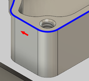
Ensure that the contour arrow points in the direction (clockwise around the part) shown in the image below. If necessary, click the arrow in your design to match.
Note: The location of the arrow is not important.
As in the previous activity, lower the bottom height by 0.01 in, and start the calculation.
Click the Heights tab
 .
.In the Bottom Height group, from the From drop-down menu select Model bottom.
Set the Offset to -0.01 in.
Note: Don’t click OK, yet. Instead proceed to the next step .
Set the linking to enable Keep Tool Down, set the maximum Stay-Down Distance to 1.25 in, and start the calculation.
Click the Linking tab
 .
.Enable the Keep Tool Down checkbox.
Set the Maximum Stay-Down Distance to 1.25 in.
Click OK to create the toolpath.
Activity 6 summary
In this activity, you reused a tool and applied a 2D Contour toolpath around the outside of the part.

Before, showing the 2D Adaptive Clearing toolpath applied around the outside of the part (left). After, showing the 2D Contour toolpath applied around the outside of the part (right).