Activity 5: Rough cut the outside of the part
In this activity, you use an Adaptive Clearing strategy to rough cut the outside of the part.

Before, showing the 2D Pocket toolpath applied in the three pockets (left). After, showing the 2D Adaptive Clearing toolpath applied around the outside of the part (right).
Prerequisites
- Activity 4 is complete.
Steps
From the 2D Adaptive command palette, confirm that the #1 – Ø1/4" flat end mill tool is still selected.
On the Manufacture toolbar, Milling tab, select 2D > 2D Adaptive Clearing
 .
.On the Tool tab
 , confirm the #1 – Ø1/4" - flat end mill tool is selected.
Select the profile of the part. This provides the geometry for the toolpath to follow.
Click the Geometry tab
 .
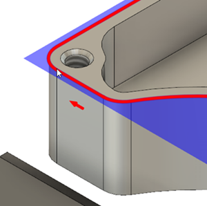
.Confirm that the Pocket Selection button is active, and click the outer profile of the part as shown in the following image:
 Tip: If may be helpful to first zoom into a corner of the part to facilitate the profile selection.
To make sure that the tool gets all the way through the stock, lower the bottom height by 0.01 in, and start the calculation.
Click the Heights tab
 .
.
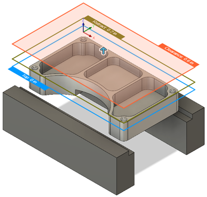
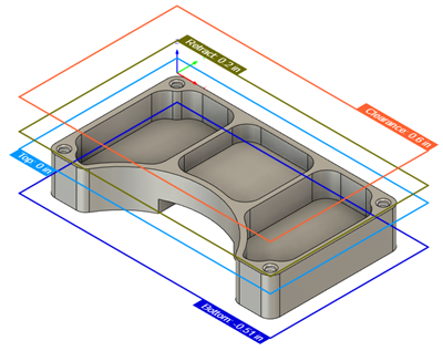
The top orange plane represents the Clearance Height. The olive green plane represents the Retract Height. The light blue plane is the Top Height.
In the Bottom Height group, from the From drop-down menu select Model bottom.
Set the Offset to -0.01 in.

Click OK to create the toolpath.
Activity 5 summary
In this activity, you reused a tool to apply a 2D Adaptive Clearing toolpath around the outside of the part.

Before, showing the 2D Pocket toolpath applied in the three pockets (left). After, showing the 2D Adaptive Clearing toolpath applied around the outside of the part (right).