Activity 7: Machine the chamfers
In this activity, you use a 2D Contour operation to create the chamfers.

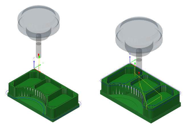
Before, showing the 2D Contour toolpath applied around the outside of the part (left). After, showing the 2D Contour toolpath applied around the chamfers on the top surface of the part (right).
Prerequisites
- Activity 6 is complete.
Steps
Select the 3 – Ø1/4" 45° (Engrave/Chamfer mill) tool.
On the Manufacture toolbar, Milling tab, select 2D > 2D Contour
 .
.On the Tool tab
 , click Select to choose a new tool.
From the Documents > 2D Adaptive Milling Tutorial v1 list, select 3 – Ø1/4" 45° (Engrave/Chamfer mill).
Click Select to close the Select Tool dialog.
Select the four chamfers on the top surface of the part and create the toolpath.
In the 2D Contour dialog, select the Geometry tab
 .
.Confirm that the Contour Selections button is active, then select all four chamfers on the top surface of the part.
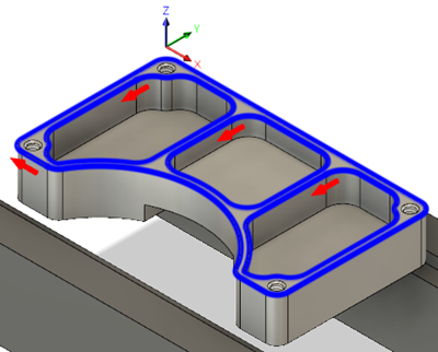
Make sure that the contour arrows point in the directions shown in the image below. Click an arrow to reverse its direction, if necessary.
Note: Arrows point clockwise for outer-contour selections and point counter-clockwise for inner-contour selections to maintain a climb cut.
Change the chamfer tip offset to 0.02 in and start the calculation.
Click the Passes tab
 .
.Set the Chamfer Tip Offset to 0.02 in.
Note: Because a chamfering tool was selected, Fusion automatically enables the Chamfer group.Click OK to create the toolpath.
Activity 7 summary
In this activity, you selected a tool and applied a 2D Contour toolpath along the four chamfers on the top surface of the part.

Before, showing the 2D Contour toolpath applied around the outside of the part (left). After, showing the 2D Contour toolpath applied around the chamfers on the top surface of the part (right).