Activity 5: Machine steep areas using contours
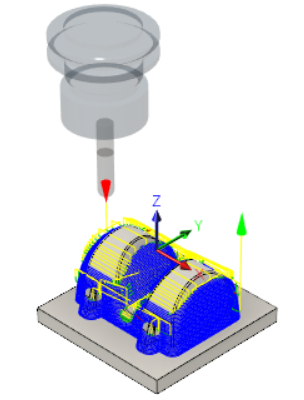
In this activity, you will use a Contour operation to machine the steep areas of the part. There remains between 0.2 mm and 0.4 mm of material left on the part (0.3 mm stock to leave plus/minus 0.1 mm tolerance). Several semi-finish operations will be used to reduce this material.

Part with 3D Pocket Clearing applied to it (left). Part after using Contour for Steep areas (right).
Prerequisites
- You have applied a 3D Pocket Clearing strategy to the part (Activity 4).
Steps
From the Contour dialog, select the #20 - Ø10 mm ball tool.
- On the Manufacture toolbar, Milling tab, select 3D > Contour
 .
. - On the Tool tab
 , click Select to access the tool library.
 - Select the tool 20 - Ø10 mm - ball from the Tutorial4 library.
- Click Select to close the Select Tool dialog.
- On the Manufacture toolbar, Milling tab, select 3D > Contour
Confine machining to steep areas only. This is achieved by limiting the slope range.
- Click the Geometry tab
 .
. - From the Tool Containment drop-down menu, select Tool Center on Boundary.
- Enable the Slope checkbox.
- Set From Slope Angle to 60 deg.
- Set To Slope Angle to 90 deg.
- Click the Geometry tab
Specify the machining passes parameters.
- Click the Passes tab
 .
. - Set Tolerance to 0.02 mm.
- Set Maximum Stepdown to 1 mm.
- Enable the Order by Depth checkbox.
- Enable the Stock to Leave checkbox. Use the default values of 0.1mm for this operation.
- Click the Passes tab
Specify the movements between passes.
- Click the Linking tab
 .
. - Select Minimum Retraction from the Retraction Policy drop-down menu.
- Set Maximum Stay-Down Distance to 10 mm.
- In the Ramp group, set Ramping Angle (deg) to 10 deg.
- Click OK to automatically start calculating the toolpath. A preview appears on the canvas.
- Click the Linking tab

Activity 5 summary
In this activity, you used a 3D Pocket Clearing strategy to remove more of the remaining material where the 20 mm tool from the previous operation could not reach.