Activity 1: Face the top
In this activity, you flatten the top surface of the block in a process called Facing.
Steps
Open the Tutorial 1 part.
- If necessary, on the Application bar, click Show Data Panel
 to show the Data Panel.
 - In the Data Panel, under Samples, double-click CAM Samples > Tutorials > Tutorial 1.
- Close the Data Panel.
- If necessary, on the Application bar, click Show Data Panel
Save a copy of the model to a personal folder.
- On the Application Bar, click File > Save As.
- Under Location, create a project or select one of the existing ones.
- Click Save.
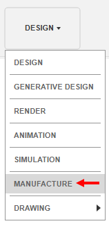
On the Design workspace toolbar, from the Workspace menu, select Manufacture.

Start a new facing operation and, from the Samples Tutorial - Metric library, select the #1 - Ø50 mm face mill tool.
On the Manufacture workspace toolbar, click Milling > 2D > Face
 .
.This creates a new Facing operation and opens the Face dialog.
On the Tool tab
 , click Select.
This opens the tool library.
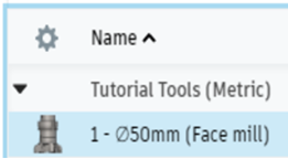
In the Libraries panel on the left, select Fusion Library > Tutorial Tools (Metric).
You may need to turn the library on.
From the list, select #1 - Ø50 mm (Face mill).

Click Select.
Verify the stock Face selection, change the Pass Extension setting to 5 mm, and start the calculation.
In the Face dialog, click the Geometry tab
 .
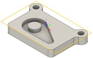
.Face assumes that the stock area is the same as the machining area. The size of the stock is shown as a yellow outline around the part. There is nothing to specify.

Click the Passes tab
 .
.Set Pass Extension to 5 mm.
The Pass Extension setting specifies the distance to extend the cut beyond the machining boundary shown in yellow.
Click OK to start the calculation and automatically create a setup with default parameters.
In the Browser, a Setup1 node is added. A setup defines various general properties for the machining operations, including the Work Coordinate System (WCS), the stock geometry, fixtures, and the machinable surfaces.
Activity 1 summary
In this activity, you selected a Facing operation, selected a tool, and flattened the top of the part.
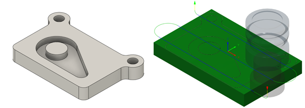
The part model (left) and the calculated toolpath with in-process stock (right) are shown below. In-process stock visualizes the effect of the toolpath on the stock material.

The toolpath is shown with a red arrow start, yellow rapid move, green lead-in and lead-out moves, blue cutting moves and a green arrow at the end.