Activity 2: Contour the part
In this activity, you create a tool and run a contouring toolpath along the outside of the part.
Prerequisites
- Activity 1 is complete.
Steps
From the 2D Contour dialog, open the Select Tool dialog.
On the Manufacture workspace toolbar, click Milling > 2D > 2D Contour
 .
.The 2D Contour dialog opens.
On the Tool tab
 , click Select.
This opens the tool library.
Create and select a new mill tool.
Click New tool
 .
.On the New tool list, under Milling, click Flat End Mill.
On the Cutter tab, in the Geometry group, set the Diameter to 8.
The edited parameter is indicated in the tool view with the blue arrow.
To be able to cut the entire height of the part, increase the Flute Length to 22 mm and the Shoulder Length to 23 mm.
Click Accept to create the tool.
Select the created tool and close the dialog tool by clicking Select.
On the Tool tab
 , set the tool’s spindle speed to 3,000 and cutting feedrate to 800.
In the Feed & Speed group, decrease the Spindle Speed to 3000 rpm.
Decrease the Cutting Feedrate to 800 mm/min.
Important: If you decide to execute this toolpath on a machine tool, set the Tool number appropriately for your machine tool changer. Set your Feed & Speed parameters based on your tooling supplier's recommendations and material type.
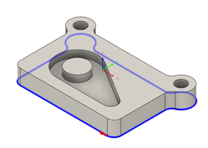
Select the bottom front edge as a chained contour.
Click the Geometry tab
 .
.Ensure that the Contour Selection button is active so that you can select the outside edge of the part geometry to run the tool around.
Move the mouse pointer over the bottom front edge.
When the edge highlights, click it. The edge is automatically selected as a chain.
Notice the blue chain around the part.
The red arrow should be on the outside pointing clockwise around the part.
 Tip: You can reverse the direction of a selected edge by clicking the red arrow.
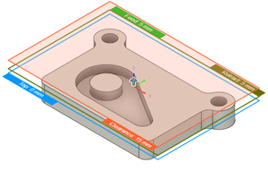
To make sure that the tool gets all the way through the stock, lower the bottom height by 1 mm and start the calculation.
Click the Heights tab
 .
.A preview of the heights is shown. The heights are color coded and labeled for easy identification.
The Bottom Height list should be set to Model Bottom.
Set the Bottom Height's Offset to -1 mm.
Click OK to start the calculation.
 Tip: You can click and drag the individual height boundaries to set the desired value.
Activity 2 summary
In this activity, you created a tool and ran a 2D Contour toolpath along the outside of the part.
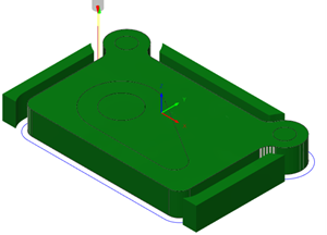
The calculated toolpath with in-process stock is shown below.

The toolpath is shown with a red arrow start, yellow rapid move, green lead-in and lead-out moves, blue cutting moves and a green arrow at the end.