Activity 4: Machine the counterbores
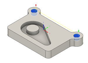
In this activity, you machine the two counterbores at the top left and right corners of the part.
Prerequisites
- Activity 3 is complete.
Steps
From the Bore dialog, select the #2 - Ø8 mm flat tool.
On the Manufacture workspace toolbar, click Milling > 2D > Bore
 .
.The Bore dialog opens.
Select the Tool tab
 .
.Be sure that #2 - Ø8 mm flat is still the active tool.
Select the geometry for the two counter bored machining areas.
In the Bore dialog, click the Geometry tab
 .
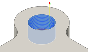
.Make sure that the Circular Face Selections button is active and set to nothing (reads Select).
Select the upper cylindrical face on the left side of the part.
If necessary, zoom in on the upper large hole.

Select the upper cylindrical face on the right side of the part.
Two faces should be selected.

Set the Pitch for the depth cut.
Click the Passes tab
 .
.Make sure the Use Ramp Angle option is deselected.
The Pitch box should now be visible.
Set the Pitch to 2 mm.
This is the depth per revolution.
Click OK to start the calculation.
Activity 4 summary
In this activity, you created a Boring toolpath to clear out the counter bored holes.
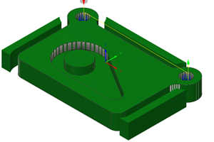
The calculated toolpath with in-process stock is shown below.

The toolpath is shown with a red arrow start, yellow rapid move, green lead-in and lead-out moves, blue cutting moves and a green arrow at the end.