Activity 5: Drill holes
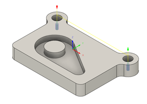
In this activity, you drill the two small holes at the top left and right corners of the work piece.
Prerequisites
- Activity 4 is complete.
Steps
Start a new Drill operation and create a drilling tool.
On the Manufacture workspace toolbar, click Milling > Drilling > Drill
 .
.The Drill dialog opens.
On the Tool tab
 , click Select.
This opens the tool library.
Click New tool
 .
.On the New tool list, under Hole making, click Drill.
Tip: You can select any type of a Hole making tool, you can change the type selection on the Cutter tab, using the Type drop-down list.On the Cutter tab, in the Geometry group, set the Diameter to 5.
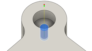
When you edit the parameter, it is indicated in the tool view with the blue arrow.
To be able to cut the entire height of the part, change the Flute Length to 22 mm.
Click Accept to create the tool.
Select the created tool and close the dialog tool by clicking Select.
Select the geometry for both holes to be drilled.
In the Drill dialog, click the Geometry tab
 .
.Verify that Selection Mode is set to Selected Faces and that the Hole Faces is active and set to Select.
If necessary, adjust the view and select the cylindrical face of the smaller diameter hole on the part.

Select the Select Same Diameter checkbox.
This automatically selects the identically sized hole at the opposite end of the part.

Drill through the part and ensure you compensate for the tip of the tool.
Click the Heights tab
 .
.Under Bottom Height, select the Drill Tip Through Bottom checkbox.
Set Break-Through Depth to 1 mm.
Selecting the drill cycle type.
Click the Cycle tab
 .
.Change the Cycle Type to Chip Breaking - Partial Retract.
Click OK to start the calculation.
Activity 5 summary
In this activity, you calculated the toolpaths for the two small drill holes at the top left and right corners of the work piece.
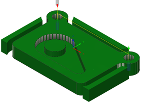
The calculated toolpath with in-process stock is shown below.

The toolpath is shown with a red arrow start, yellow rapid move, green lead-in and lead-out moves, blue cutting moves and a green arrow at the end.