Activity 4: Finish cut the three pockets
In this activity, you finish cut the three pockets using a 2D Pocket toolpath.

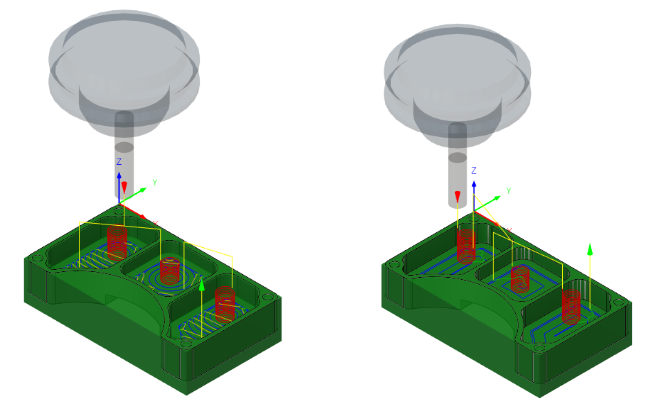
Before, showing the 2D Adaptive Clearing toolpath applied in the three pockets (left). After, showing the 2D Pocket toolpath applied in the three pockets (right).
Prerequisites
- Activity 3 is complete.
Steps
From the 2D Pocket dialog, confirm that the #1 – Ø1/4" flat tool is still selected.
On the Manufacture toolbar, Milling tab, select 2D > 2D Pocket
 .
.On the Tool tab
 , confirm the #1 – Ø1/4" flat end mill tool is selected.
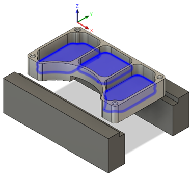
Select the three faces at the bottom of the pockets.
In the 2D Pocket dialog, select the Geometry tab
 .
.Click the Pocket Selection button and select the three faces at the bottom of the part.

Set the passes to enable Finishing Passes, with a Stepover of 0.025 in, a Maximum Stepover of 0.125 in, and a Finish Feedrate of 60 in/min. Be sure to clear Stock to Leave.
Select the Passes tab
 .
.Enable the Finishing Passes checkbox.
Confirm that Stepover is set to 0.025 in.
Confirm that Finish Feedrate is set to 60 in/min.
Change Maximum Stepover to 0.125 in.
Deselect the Stock To Leave checkbox.
Set the linking to a Maximum Stay-Down Distance of 1.25 in. Enable the Lead-In (Entry), and set the Horizontal Lead-In Radius, the Vertical Lead-In Radius, and the Linear Lead-In Distance to 0.025 in. Change the Maximum Ramp Stepdown to 0.0625 in, set the Helical Ramp Diameter and Minimum Ramp Diameter to 0.2375 in, and create the toolpath.
Click the Linking tab
 .
.Set the Maximum Stay-Down Distance to 1.25 in.
From the Leads & Transitions group, enable the Lead-In (Entry) checkbox.
Set the Horizontal Lead-In Radius to 0.025 in.
Set the Linear Lead-In Distance to 0.025 in.
Set the Vertical Lead-In Radius to 0.025 in.
From the Ramp group, set the Maximum Ramp Stepdown to 0.625 in.
Set the Helical Ramp Diameter to 0.2375 in.
Set the Minimum Ramp Diameter to 0.2375 in.
Click OK to create the toolpath.
Activity 4 summary
In this activity, you reused a tool to apply a 2D Pocket toolpath in the three pockets of the part.

Before, showing the 2D Adaptive Clearing toolpath applied in the three pockets (left). After, showing the 2D Pocket toolpath applied in the three pockets (right).