Activity 8: Parallel finishing
In this activity, we will use the Parallel strategy to cut equally spaced rows, inside the machining boundary.
The cuts are parallel in the machining plane and follow the surface up or down, in the Z direction. Parallel passes are best suited for the finishing of shallow areas and down-milling cuts.
Prerequisites
- Activity 7 is complete.
Steps
Start a new 3D Parallel operation and verify that Tool #21 - Ø6 mm R3 mm ball is still the active tool.
- On the Manufacture toolbar, Milling tab, select 3D > Parallel
 .
. - Select the Tool tab
 .
. - Be sure Tool #21 - Ø6 mm R3 mm (Ball end mill) is still the active tool.
- On the Manufacture toolbar, Milling tab, select 3D > Parallel
Containment of the machining area and angled wall slope control.
In the Parallel dialog, go to the Geometry tab
 .
.Enable the Slope checkbox.
Set To Slope Angle to 35 degrees. This limits machining to faces from 0° (horizontal) to 35°. Since the last toolpath used From Slope Angle 30° to 90°, this provides a 5° overlap between the toolpaths.
In the Surface Manager group, click
 to add a surface group. The Faces dialog opens.
With the Selection button active, select all of the flat faces as shown in the image below.
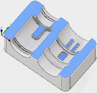
From the Action group of buttons, select Avoid.
Click OK.
Limit the toolpath area to cut below the Top.
- Click the Heights tab
 .
. - The Top height drop-down list should be set to Model Top.
- Set the Top height Offset to -1 mm. Since we Face milled the top, this area is already machined. The Offset ensures the toolpaths will start below the top face of the part.
- Click the Heights tab
Stepover cut value, cut angle.
- Click the Passes tab
 .
. - Set Stepover to .2 mm.
- Set Pass Direction to 45 degrees.
- Click the Passes tab
Controlling the rapid retract clearance method.
- Click the Linking tab
 .
. - Set the Retraction Policy drop-down list to Minimum retraction.
- Set Safe Distance to 6 mm.
- In the Leads & Transitions group, set the Transition Type drop-down list to Straight line.
- Click OK to start the calculation.
- Click the Linking tab
Activity 8 summary
In this activity you created a Parallel finishing operation with a slope angle that overlaps the previous toolpath, excluded flat faces using Surface Manager, and limited the top height with an offset.
| The calculated toolpath is shown below. | The simulated toolpath is shown below. |
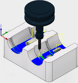 |
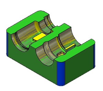 |
The toolpath is shown with a red arrow start, yellow rapid move, green lead in/out move, blue cutting moves and a green arrow at the end.