Activity 7: Cavity Contour
In this activity, we will start the finishing process with 3D Contour. This will finish the cavity walls.
Prerequisites
- Activity 6 is complete.
Steps
Start a new 3D Contour operation and, from the Tutorial Tools (Metric) library, select the #21 - Ø6 mm R3 mm ball tool.
- On the Manufacture toolbar, Milling tab, select 3D > Contour
 .
. - On the Tool tab
 , click Select. This opens the tool library.
 - In the Library, select Samples > Tutorial – Metric
- From the list, select #21 - Ø6 mm R3 mm (Ball end mill).
- Click Select.
- On the Manufacture toolbar, Milling tab, select 3D > Contour
Containment of the machining area and angled wall slope control.
- In the 3D Contour command palette, click the Geometry tab
 .
. - From the Tool Containment drop-down list, select Tool center on boundary. This will keep the toolpath within the shadow edge boundary of the model.
- Set Additional Offset to 1 mm.
- Enable the Slope checkbox.
- Set From Slope Angle to 30 degrees.*. This will limit machinable faces that range from 30 deg. horizontal, to 90 deg. vertical.
- In the 3D Contour command palette, click the Geometry tab
Depth cut settings, flat area detection.
- Click the Passes tab
 .
. - Set Maxiumum Stepdown to .3 mm.
- Disable the Flat area detection checkbox.
- Click the Passes tab
Controlling the rapid retract clearance method.
- Click the Linking tab
 .
. - Set the Retraction Policy drop-down list to Minimum retraction.
- Set Safe Distance to 5 mm.
- Set Maximum Stay Down Distance to 8 mm.
- Click OK to start the calculation.
- Click the Linking tab
Activity 7 summary
In this activity you selected a 3D Contour finishing operation, selected a library tool, contained the toolpath, restricted the angle of the walls it will machine.
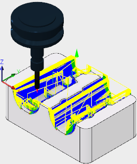
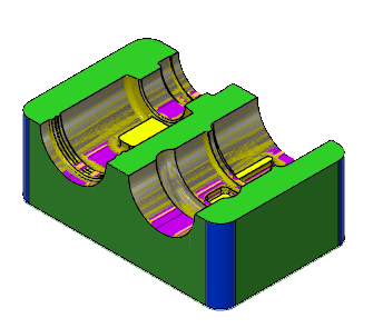
| The calculated toolpath is shown below. | The simulated toolpath is shown below. |
 |
 |
The toolpath is shown with a red arrow start, yellow rapid move, green lead in/out move, blue cutting moves and a green arrow at the end.