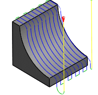
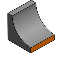
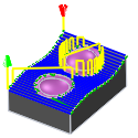
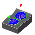
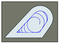
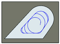
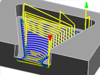
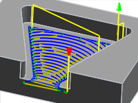
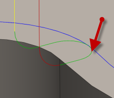
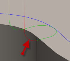
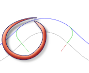
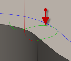
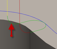
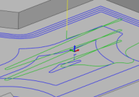
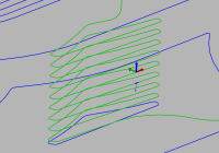
Contour Finishing reference
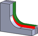
Creates XY profiles around a projected waterline at multiple Z heights.
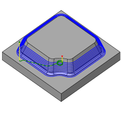
Manufacture > Milling > 3D > Contour ![]()
The Z steps are apart in Z by the stepdown parameter.
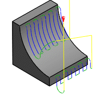
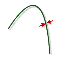
Contour finishing is most effective when machining steep areas of the part. As with all finishing strategies, the machining can be limited by a tool contact angle. You can use this method to restrict contour finishing passes to steep areas.
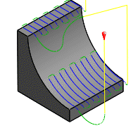
The cutting paths can be smoothed in corners by a horizontal maximum deviation rather than a fixed radius. This means that sharp corners tend to have very small smoothing radii in them, because a bigger arc would deviate too far from the corner. This method represents a compromise between the requirements of high speed machining, and the need to respect the specified tolerance.
 Tool tab settings

Coolant
Select the type of coolant used with the machine tool. Not all types will work with all machine postprocessors.
Feed & Speed
Spindle and Feedrate cutting parameters.
- Spindle Speed - The rotational speed of the spindle expressed in Rotations Per Minute (RPM)
- Surface Speed - The speed which the material moves past the cutting edge of the tool (SFM or m/min)
- Ramp Spindle Speed - The rotational speed of the spindle when performing ramp movements
- Cutting Feedrate - Feedrate used in regular cutting moves. Expressed as Inches/Min (IPM) or MM/Min
- Feed per Tooth - The cutting feedrate expressed as the feed per tooth (FPT)
- Lead-In Feedrate - Feed used when leading in to a cutting move.
- Lead-Out Feedrate - Feed used when leading out from a cutting move
- Ramp Feedrate - Feed used when doing helical ramps into stock
- Plunge Feedrate - Feed used when plunging into stock
- Feed per Revolution - The plunge feedrate expressed as the feed per revolution
Shaft & Holder
When enabled, this provides additional controls for collision handling. Collision detection can be done for both the tool shaft and holder, and they can be given separate clearances. Choose between several modes, depending on the machining strategy.
This function increases the number of calculations that need to be performed. This may effect the performance of your system on very large projects.
Shaft and Holder Modes
Disabled - When Shaft and Holder is disabled Fusion does not calculate for any shaft/holder collisions.
Pull away - The toolpath pulls away from the workpiece to maintain a safe distance between the shaft and/or holder.
Detect tool length - The tool is automatically extended further out of the holder to maintain the specified safe distance between the shaft and/or holder and the workpiece. A message indicating how the far the tool is extended out of the holder is logged.
Fail on collision - The toolpath calculation is aborted and an error message logged when the safe distance is violated.
Settings
- Use Shaft - Enable to include the shaft of the selected tool, in the toolpath calculation, to avoid collisions.
- Shaft Clearance - The tool shaft always stays this distance from the part.
- Use Holder - Enable to include the holder of the selected tool, in the toolpath calculation, to avoid collisions.
- Holder Clearance - The tool holder always stays this distance from the part.
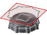
 Geometry tab settings
Machining Boundary
Boundaries mode specifies how the toolpath boundary is defined. The following images are shown using a 3D Radial toolpath.
Example 1
Example 2
Boundary modes:
None - The toolpaths machine all stock without limitation.
Bounding box - Contains toolpaths within a box defined by the maximum extents of the part as viewed from the WCS.
Bounding box
Silhouette - Contains toolpaths within a boundary defined by the part shadow as viewed from the WCS.
Silhouette
Selection - Contains toolpaths within a region specified by a selected boundary.
Selection
Tool Containment
Use tool containment to control the tools' position in relation to the selected boundary or boundaries.
Inside
The entire tool stays inside the boundary. As a result, the entire surface contained by the boundary might not be machined.
Inside
Center
The boundary limits the center of the tool. This setting ensures that the entire surface inside the boundary is machined. However, areas outside the boundary or boundaries might also be machined.
Center
Outside
The toolpath is created inside the boundary, but the tool edge can move on the outside edge of the boundary.
Outside
To offset the boundary containment, use the Additional Offset parameter.
Additional Offset
The additional offset is applied to the selected boundary/boundaries and tool containment.
A positive value offsets the boundary outwards unless the tool containment is Inside, in which case a positive value offsets inwards.
Negative offset with tool center on boundary
No offset with tool center on boundary
Positive offset with tool center on boundary
To ensure that the edge of the tool overlaps the boundary, select the Outside tool containment method and specify a small positive value.
To ensure that the edge of the tool is completely clear of the boundary, select the Inside tool containment method and specify a small positive value.
Contact Point Boundary
When enabled, specifies that the boundary limits where the tool touches the part rather than the tool center location.
Disabled
Enabled
The difference is illustrated below on a Parallel toolpath using a ball end mill.
Disabled
Enabled
Contact Only
Controls whether or not toolpaths are generated where the tool is not in contact with the machining surface. When disabled, toolpaths are extended to the limits of the containment boundary and across openings in the workpiece.
Enabled
Disabled
Slope
Contains toolpaths based on a range of specified angles.
0° - 90°
0° - 45°
45° - 90°
Slope angle confinement is specified by the From Slope Angle and To Slope Angle angle parameters on the Geometry tab. Angles are defined from 0° (horizontal) to 90° (vertical).
Only areas equal to or greater than the values in the From Slope Angle and To Slope Angle parameters are machined.
Most 3D finishing strategies support slope angle confinement. One use of slope confinement is to confine a selected toolpath strategy to angles where it works best. For example, Parallel Finish is better suited to shallow areas while Contour Finish is better suited to steep areas.
From Slope Angle
From Slope Angle is defined from the 0° (horizontal) plane. Only areas equal to or greater than this value are machined.
Slope angle from 0°
To Slope Angle
To Slope Angle is defined from the 0° (horizontal) plane. Only areas equal to or less than this value are machined.
Slope angle to 90°
Rest Machining
Limits the operation to just remove material that a previous tool or operation could not remove.
Rest Machining ON
Rest Machining OFF
Source
Specifies the source from which the rest machining is to be calculated.
- From previous operation(s)
- From operation(s)
- From tool
- From file
- From solid(s)
- From setup stock
From Setup Stock
Union of all Dependent Operations
Union of all dependent operations.
Include all Previous Operations
Include all previous operations.
Tool Diameter
Specifies the diameter of the rest material tool.
Corner Radius
Specifies the corner radius of the rest material tool.
Taper Angle
Specifies the rest material tool taper angle.
Shoulder Length
Specifies the rest material tool shoulder length.
File
Specifies the rest material file.
Ignore Stock Less Than
Specifies the amount of stock from previous operations to ignore. Expressed in distance units. The parameter helps you avoid machining of minor rest material.
Tool Orientation
Specifies how the tool orientation is determined using a combination of triad orientation and origin options.
The Orientation drop-down menu provides the following options to set the orientation of the X, Y, and Z triad axes:
- Setup WCS orientation - Uses the workpiece coordinate system (WCS) of the current setup for the tool orientation.
- Model orientation - Uses the coordinate system (WCS) of the current part for the tool orientation.
- Select Z axis/plane & X axis - Select a face or an edge to define the Z axis and another face or edge to define the X axis. Both the Z and X axes can be flipped 180 degrees.
- Select Z axis/plane & Y axis - Select a face or an edge to define the Z axis and another face or edge to define the Y axis. Both the Z and Y axes can be flipped 180 degrees.
- Select X & Y axes - Select a face or an edge to define the X axis and another face or edge to define the Y axis. Both the X and Y axes can be flipped 180 degrees.
- Select coordinate system - Sets a specific tool orientation for this operation from a defined user coordinate system in the model. This uses both the origin and orientation of the existing coordinate system. Use this if your model does not contain a suitable point & plane for your operation.
The Origin drop-down menu offers the following options for locating the triad origin:
- Setup WCS origin - Uses the workpiece coordinate system (WCS) origin of the current setup for the tool origin.
- Model origin - Uses the coordinate system (WCS) origin of the current part for the tool origin.
- Selected point - Select a vertex or an edge for the triad origin.
- Stock box point - Select a point on the stock bounding box for the triad origin.
- Model box point - Select a point on the model bounding box for the triad origin.
Model
Enable to override the model geometry (surfaces/bodies) defined in the setup.
Include Setup Model
Enabled by default, the model selected in the setup is included in addition to the model surfaces selected in the operation. If you disable this checkbox, then the toolpath is generated only on the surfaces selected in the operation.
Avoid/Touch Surfaces
Specifies surfaces to avoid. When enabled, toolpaths stay away from the selected surfaces by a specified amount.
Disabled
Enabled
Avoid/Touch Surface Clearance
The tool always stays this distance from the selected surfaces.
Touch Surfaces
Inverts the meaning of the Avoid surfaces setting. When enabled, the avoid surfaces are the ones that must be touched within the given clearance while the remaining surfaces are avoided.
Touch surfaces
 Heights tab settings
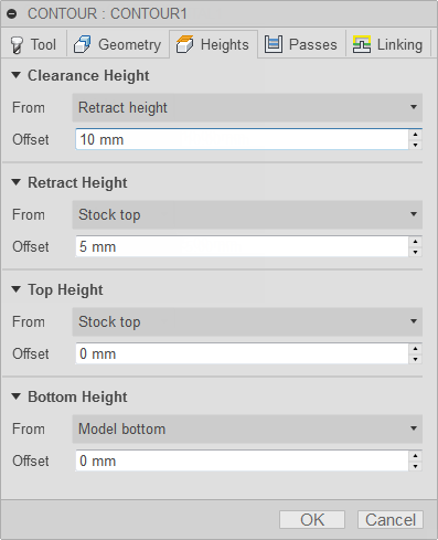
Clearance Height
The Clearance height is the first height the tool rapids to on its way to the start of the tool path.
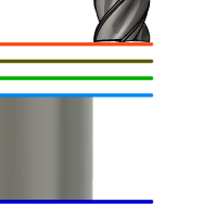
Clearance Height
- Retract height: incremental offset from the Retract Height.
- Feed height: incremental offset from the Feed Height.
- Top height: incremental offset from the Top Height.
- Bottom height: incremental offset from the Bottom Height.
- Model top: incremental offset from the Model Top.
- Model bottom: incremental offset from the Model Bottom.
- Stock top: incremental offset from the Stock Top.
- Stock bottom: incremental offset from the Stock Bottom.
- Selection: incremental offset from a Point (vertex), Edge or Face selected on the model.
- Origin (absolute): absolute offset from the Origin that is defined in either the Setup or in Tool Orientation within the specific operation.
Clearance Height Offset
The Clearance Height Offset is applied and is relative to the Clearance height selection in the above drop-down list.
Retract Height
Retract height sets the height that the tool moves up to before the next cutting pass. Retract height should be set above the Feed height and Top. Retract height is used together with the subsequent offset to establish the height.
Retract Height
- Clearance height: incremental offset from the Clearance Height.
- Feed height: incremental offset from the Feed Height.
- Top height: incremental offset from the Top Height.
- Bottom height: incremental offset from the Bottom Height.
- Model top: incremental offset from the Model Top.
- Model bottom: incremental offset from the Model Bottom.
- Stock top: incremental offset from the Stock Top.
- Stock bottom: incremental offset from the Stock Bottom.
- Selection: incremental offset from a Point (vertex), Edge or Face selected on the model.
- Origin (absolute): absolute offset from the Origin that is defined in either the Setup or in Tool Orientation within the specific operation.
Retract Height Offset
Retract Height Offset is applied and is relative to the Retract height selection in the above drop-down list.
Top Height
Top height sets the height that describes the top of the cut. Top height should be set above the Bottom. Top height is used together with the subsequent offset to establish the height.
Top Height
- Clearance height: incremental offset from the Clearance Height.
- Retract height: incremental offset from the Retract Height.
- Feed height: incremental offset from the Feed Height.
- Bottom height: incremental offset from the Bottom Height.
- Model top: incremental offset from the Model Top.
- Model bottom: incremental offset from the Model Bottom.
- Stock top: incremental offset from the Stock Top.
- Stock bottom: incremental offset from the Stock Bottom.
- Selection: incremental offset from a Point (vertex), Edge or Face selected on the model.
- Origin (absolute): absolute offset from the Origin that is defined in either the Setup or in Tool Orientation within the specific operation.
Top offset
Top Offset is applied and is relative to the Top height selection in the above drop-down list.
Bottom Height
Bottom height determines the final machining height/depth and the lowest depth that the tool descends into the stock. Bottom height needs to be set below the Top. Bottom height is used together with the subsequent offset to establish the height.
Bottom Height
- Clearance height: incremental offset from the Clearance Height.
- Retract height: incremental offset from the Retract Height.
- Feed height: incremental offset from the Feed Height.
- Top height: incremental offset from the Top Height.
- Model top: incremental offset from the Model Top.
- Model bottom: incremental offset from the Model Bottom.
- Stock top: incremental offset from the Stock Top.
- Stock bottom: incremental offset from the Stock Bottom.
- Selection: incremental offset from a Point (vertex), Edge or Face selected on the model.
- Origin (absolute): absolute offset from the Origin that is defined in either the Setup or in Tool Orientation within the specific operation.
Bottom Offset
Bottom Offset is applied and is relative to the Bottom height selection in the above drop-down list.
 Passes tab settings
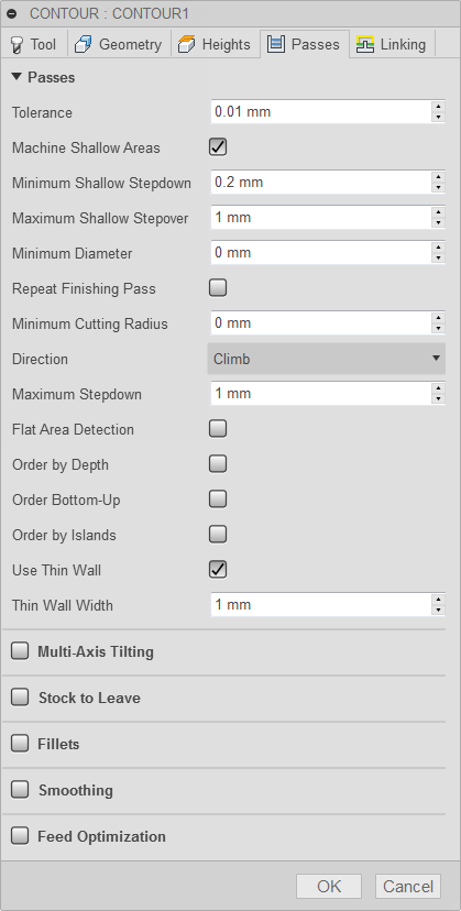
Tolerance
The machining tolerance is the sum of the tolerances used for toolpath generation and geometry triangulation. Any additional filtering tolerances must be added to this tolerance to get the total tolerance.
 |
 |
| Loose Tolerance .100 | Tight Tolerance .001 |
CNC machine contouring motion is controlled using line G1 and arc G2 G3 commands. To accommodate this, Fusion approximates spline and surface toolpaths by linearizing them creating many short line segments to approximate the desired shape. How accurately the toolpath matches the desired shape depends largely on the number of lines used. More lines result in a toolpath that more closely approximates the nominal shape of the spline or surface.
Data Starving
It is tempting to always use very tight tolerances, but there are trade-offs including longer toolpath calculation times, large G-code files, and very short line moves. The first two are not much of a problem because Fusion calculates very quickly and most modern controls have at least 1MB of RAM. However, short line moves, coupled with high feedrates, may result in a phenomenon known as data starving.
Data starving occurs when the control becomes so overwhelmed with data that it cannot keep up. CNC controls can only process a finite number of lines of code (blocks) per second. That can be as few as 40 blocks/second on older machines and 1,000 blocks/second or more on a newer machine like the Haas Automation control. Short line moves and high feedrates can force the processing rate beyond what the control can handle. When that happens, the machine must pause after each move and wait for the next servo command from the control.
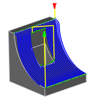
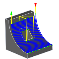
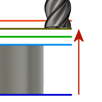
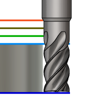
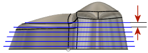
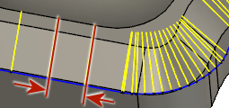
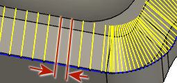
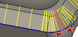
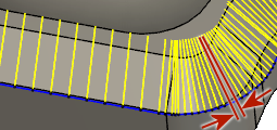
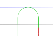
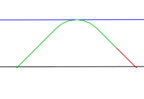
Machine Shallow Areas
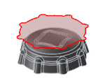
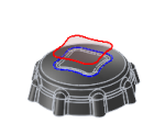
Specifies that additional Z-levels should be cuts at shallow areas. The following two images are shown with 3D Contour.
 |
 |
| Disabled | Enabled |
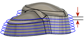
Minimum Shallow Stepdown
This parameter controls the minimum allowed stepdown between the extra Z-levels. It takes precedence over the Maximum Shallow Stepover value.
Maximum Shallow Stepover
This parameter controls the stepover used to detect areas where extra Z-levels should be inserted. If the normal stepdown results in a stepover of more than this value, extra levels are inserted until the stepover or the minimum stepdown is reached.
Minimum Diameter
The smallest cylindrical diameter that can be machined. The value becomes effective when set to anything larger than the difference between the cavity dia, minus the tool diameter.
 |
 |
| Set to Zero | Set to .320 in |
| Cuts to full depth | Greater than, Cavity dia. - Tool dia. |
Repeat Finishing Pass
Enable to perform the final finishing pass twice to remove stock left due to tool deflection.
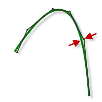
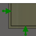
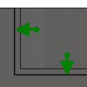
Minimum Cutting Radius
Defines the smallest toolpath radius to generate in a sharp corner. Minimum Cutting Radius creates a blend at all inside sharp corners.
Forcing the tool into a sharp corner, or a corner where the radius is equal to the tool radius, can create chatter and distort the surface finish.
 |
 |
|
| Set to Zero - The toolpath is forced into all inside sharp corners. | Set to 0.07 in - The toolpath will have a blend of .070 radius in all sharp corners. |
Direction
The Direction option lets you control if Fusion should try to maintain either Climb or Conventional milling.
Climb
Select Climb to machine all the passes in a single direction. When this method is used, Fusion attempts to use climb milling relative to the selected boundaries.
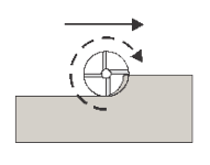
Climb
Conventional
This reverses the direction of the toolpath compared to the Climb setting to generate a conventional milling toolpath.
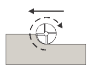
Conventional
Maximum Stepdown
Specifies the distance for the maximum stepdown between Z-levels. The maximum stepdown is applied to the full depth, less any remaining stock and finish pass amounts.
 |
 |
- The final pass may be less than the Max Stepdown.
- Shown without finishing stepdown.
Flat Area Detection
If enabled, the strategy attempts to detect the heights of flat areas and peaks, and machine at these levels.
If disabled, the strategy machines at exactly the specified stepdowns.
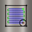
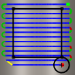
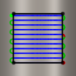
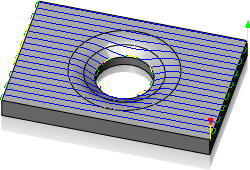
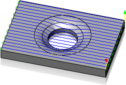
Order by Depth
When enabled, this orders the cuts of multiple contours or cavities by Z level.
 |
 |
| Model with multiple cavity selections |
All cavities cut by Z level |
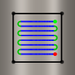
Order Bottom-Up
Contour passes are usually ordered from top to bottom. Enable this checkbox to specify that passes should be ordered bottom-up (bottom to top).
Ordering is done so that the passes with the smallest Z-level tool orientation are done first in one operation for multiple contours. This method is very useful for machining fragile materials like graphite.
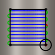
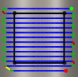
Order by Islands
Specifies the order in which depth cuts are taken when there are multiple profiles.

Disabled
Disabled - Depth cuts are ordered by depth.

Enabled
Enabled - Depth cuts are ordered by profile.
Use Thin Wall
When milling part features with wall thicknesses comparable to sheet metal stock, or even thinner, the stock is subjected to the forces generated by metal removal. This can result in the delicate structure of thin walls moving relative to the tool, making it difficult to maintain dimensional accuracy and impart the specified surface finish.
This option can be used to reduce the vibration and chatter by ensuring that both sides of a thin wall are machined at the same time.
Thin Wall Width
The width of walls that should be considered thin walls.
Any wall with this width or thinner is machined on both sides at the same time to reduce vibration and chatter.
Multi-Axis Tilting
Enables multi-axis tilt to avoid collision with the holder when using short tools.
Maximum Tilt
Specifies the maximum allowed tilt from the selected operation tool axis.
Maximum Segment Length
Specifies the maximum length of a single segment for the generated toolpath.
 |
 |
| Segment distance .150 in | Segment distance .050 in |
Maximum Tool Axis Sweep
Specifies the maximum angle change in a single tool axis sweep for the generated toolpath.
 |
 |
| Angular sweep of 10 degrees | Angular sweep of 5 degrees |
Stock to Leave
Positive
Positive Stock to Leave - The amount of stock left after an operation to be removed by subsequent roughing or finishing operations. For roughing operations, the default is to leave a small amount of material.

None
No Stock to Leave - Remove all excess material up to the selected geometry.
 Negative
Negative Stock to Leave - Removes material beyond the part surface or boundary. This technique is often used in Electrode Machining to allow for a spark gap, or to meet tolerance requirements of a part.
Radial (wall) Stock to Leave
The Radial Stock to Leave parameter controls the amount of material to leave in the radial (perpendicular to the tool axis) direction, i.e. at the side of the tool.
Radial stock to leave
Radial and axial stock to leave
Specifying a positive radial stock to leave results in material being left on the vertical walls and steep areas of the part.
For surfaces that are not exactly vertical, Fusion interpolates between the axial (floor) and radial stock to leave values, so the stock left in the radial direction on these surfaces might be different from the specified value, depending on surface slope and the axial stock to leave value.
Changing the radial stock to leave automatically sets the axial stock to leave to the same amount, unless you manually enter the axial stock to leave.
For finishing operations, the default value is 0 mm / 0 in, i.e. no material is left.
For roughing operations, the default is to leave a small amount of material that can then be removed later by one or more finishing operations.
Negative stock to leave
When using a negative stock to leave, the machining operation removes more material from your stock than your model shape. This can be used to machine electrodes with a spark gap, where the size of the spark gap is equal to the negative stock to leave.
Both the radial and axial stock to leave can be negative numbers. However, the negative radial stock to leave must be less than the tool radius.
When using a ball or radius cutter with a negative radial stock to leave that is greater than the corner radius, the negative axial stock to leave must be less than or equal to the corner radius.
Axial (floor) Stock to Leave
The Axial Stock to Leave parameter controls the amount of material to leave in the axial (along the Z-axis) direction, i.e. at the end of the tool.
Axial stock to leave
Both radial and axial stock to leave
Specifying a positive axial stock to leave results in material being left on the shallow areas of the part.
For surfaces that are not exactly horizontal, Fusion interpolates between the axial and radial (wall) stock to leave values, so the stock left in the axial direction on these surfaces might be different from the specified value depending on surface slope and the radial stock to leave value.
Changing the radial stock to leave automatically sets the axial stock to leave to the same amount, unless you manually enter the axial stock to leave.
For finishing operations, the default value is 0 mm / 0 in, i.e. no material is left.
For roughing operations, the default is to leave a small amount of material that can then be removed later by one or more finishing operations.
Negative stock to leave
When using a negative stock to leave the machining operation removes more material from your stock than your model shape. This can be used to machine electrodes with a spark gap, where the size of the spark gap is equal to the negative stock to leave.
Both the radial and axial stock to leave can be negative numbers. However, when using a ball or radius cutter with a negative radial stock to leave that is greater than the corner radius, the negative axial stock to leave must be less than or equal to the corner radius.
Fillets
Enable to enter a fillet radius.
Fillet Radius
Specify a fillet radius.
Smoothing
Smooths the toolpath by removing excessive points and fitting arcs where possible within the given filtering tolerance.
 |
 |
| Smoothing Off | Smoothing On |
Smoothing is used to reduce code size without sacrificing accuracy. Smoothing works by replacing collinear lines with one line and tangent arcs to replace multiple lines in curved areas.
The effects of smoothing can be dramatic. G-code file size may be reduced by as much as 50% or more. The machine will run faster and more smoothly and surface finish improves. The amount of code reduction depends on how well the toolpath lends itself to smoothing. Toolpaths that lay primarily in a major plane (XY, XZ, YZ), like parallel paths, filter well. Those that do not, such as 3D Scallop, are reduced less.
Smoothing Tolerance
Specifies the smoothing filter tolerance.
Smoothing works best when the Tolerance (the accuracy with which the original linearized path is generated) is equal to or greater than the Smoothing (line arc fitting) tolerance.
Feed Optimization
Specifies that the feed should be reduced at corners.
Maximum Directional Change
Specifies the maximum angular change allowed before the feedrate is reduced.
Reduced Feed Radius
Specifies the minimum radius allowed before the feed is reduced.
Reduced Feed Distance
Specifies the distance to reduce the feed before a corner.
Reduced Feedrate
Specifies the reduced feedrate to be used at corners.
Only Inner Corners
Enable to only reduce the feedrate on inner corners.
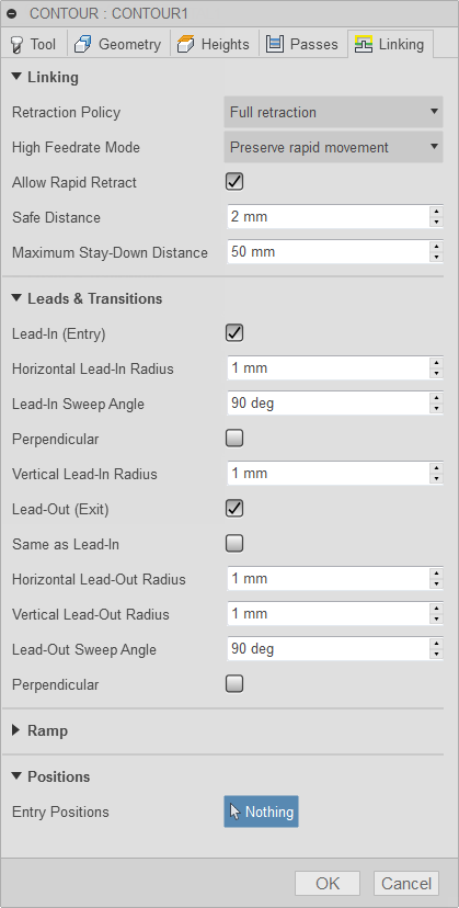
 Linking tab settings
Retraction Policy
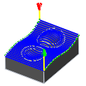
Controls how the tool moves between cutting passes. The following images are shown using the Flow strategy.
Full retraction - completely retracts the tool to the Retract Height at the end of the pass before moving above the start of the next pass.
Minimum retraction - moves straight up to the lowest height where the tool clears the workpiece, plus any specified safe distance.

Shortest path - moves the tool the shortest possible distance in a straight line between paths.
 Important: The Shortest path option should not be used on machines that do not support linearized rapid movements where G0 moves are straight-line (versus G0 moves that drive all axes at maximum speed, sometimes referred to as "dogleg" moves). Failure to obey this rule will result in machine motion that cannot be properly simulated by the software and may result in tool crashes.
For CNC machines that do not support linearized rapid moves, the post processor can be modified to convert all G0 moves to high-feed G1 moves. Contact technical support for more information or instructions how to modify post processors as described.
High Feedrate Mode
Specifies when rapid movements should be output as true rapids (G0) and when they should be output as high feedrate movements (G1).
- Preserve rapid movement - All rapid movements are preserved.
- Preserve axial and radial rapid movement - Rapid movements moving only horizontally (radial) or vertically (axial) are output as true rapids.
- Preserve axial rapid movement - Only rapid movements moving vertically.
- Preserve radial rapid movement - Only rapid movements moving horizontally.
- Preserve single axis rapid movement - Only rapid movements moving in one axis (X, Y or Z).
- Always use high feed - Outputs rapid movements as (high feed moves) G01 moves instead of rapid movements (G0).
This parameter is usually set to avoid collisions at rapids on machines which perform "dog-leg" movements at rapid.
High Feedrate
The feedrate to use for rapids movements output as G1 instead of G0.
Allow Rapid Retract
When enabled, retracts are done as rapid movements (G0). Disable to force retracts at lead-out feedrate.
Safe Distance
Minimum distance between the tool and the part surfaces during retract moves. The distance is measured after stock to leave has been applied, so if a negative stock to leave is used, special care should be taken to ensure that safe distance is large enough to prevent any collisions.
Maximum Stay-Down Distance
Specifies the maximum distance allowed for stay-down moves.
1" Maximum stay-down distance
2" Maximum stay-down distance
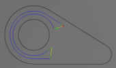
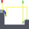
Lead-In (Entry)
Enable to generate a lead-in.
Lead-in
Horizontal Lead-In Radius
Specifies the radius for horizontal lead-in moves.
Horizontal lead-in radius
Lead-In Sweep Angle
Specifies the sweep of the lead-in arc.
Sweep angle @ 90 degrees
Sweep angle @ 45 degrees
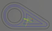
Perpendicular
Replaces tangential extensions of lead-in/lead-out arcs with a move perpendicular to the arc.
Shown with Perpendicular entry/exit
Example: A bore that has lead arcs that are as large as possible (the larger the arc the less chance of dwell mark), and where a tangent linear lead is not possible because it would extend into the side of the bore.
Vertical Lead-In Radius
The radius of the vertical arc smoothing the entry move as it goes from the entry move to the toolpath itself.
Vertical lead-in radius
Lead-Out (Exit)
Enable to generate a lead-out.
Lead-out
Same as Lead-In
Specifies that the lead-out definition should be identical to the lead-in definition.
Horizontal Lead-Out Radius
Specifies the radius for horizontal lead-out moves.
Horizontal lead-out radius
Vertical Lead-Out Radius
Specifies the radius of the vertical lead-out.
Vertical lead-out radius
Lead-Out Sweep Angle
Specifies the sweep of the lead-out arc.
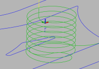
Ramp Type
Specifies how the cutter moves down for each depth cut.
Predrill
Plunge
Zig-Zag
Notice the smooth transitions on the Zig-Zag ramp type.
Profile
Smooth Profile
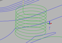
Helix
Transition Type
Specifies the type of connection done between passes.
- No contact - Sidesteps are not connected with each other on the same Z-level, but connected with a retract move.
- Straight line - Simpler, direct connections using straight lines.
- Shortest path - The shortest possible path between machining areas - typically a move in a straight line.
- Smooth - Use smooth tangential movements using true arcs where appropriate.
Ramping Angle (deg)
Specifies the maximum ramping angle.
Maximum Ramp Stepdown
Specifies the maximum stepdown per revolution on the ramping profile. This parameter allows the tool load to be constrained when doing full-width cuts during ramping.
Ramp Clearance Height
Height of ramp over the current stock level.
Helical Ramp Diameter
Specifies the helical ramp diameter.
Smooth Ramps
When enabled, ramps are started and ended tangentially in all three axes.
Ramping is done without discontinuities in the first order derivative so that smooth curves are used instead of the usual kinks in the path.
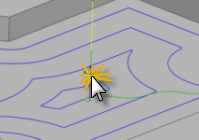
Entry positions
Selection button to choose entry positions.