Generate a 3+2 Roughing toolpath
This feature is part of an extension. Extensions are a flexible way to access additional capabilities in Fusion. Learn more.
On the Manufacture workspace toolbar, click Milling > 3D > 3+2 Roughing
 .
.The 3+2 Roughing dialog opens.
On the Tool tab, click Select to pick a tool. If you have not created a tool to use, in the left panel of the Tool Library dialog, pick a tool from the Fusion Library.
Note: To machine difficult areas such as undercuts, use short, rigid tools.On the Multi-Axis tab, select a Machining Type, then configure the options for that type:
5-axis — Under Tool Axis, select a Primary Mode (Automatic, Semi-automatic, or Selection). For Selection, click Select and choose faces on the part.
Polar — In the Polar Machining group, choose Mode (Prefer in control or In computer). For In computer, specify Line Angle. For more information, see Polar machining.
3-axis — On the Geometry tab, use Machining Boundary to define the area to machine.
(5-axis only) Under Tool Axis, select a Primary Mode option:
Automatic - Useful for machining complex parts. The strategy determines the most suitable tool orientations based on searching criteria.
Semi-automatic - Useful for machining complex parts, if you need the tool to machine using specific orientations first. The strategy uses the tool orientations that you specify for initial machining, then automatically determines other orientations to remove more stock.
Selection - Useful for machining simpler parts where you can determine the most effective tool orientations to use, like prismatic parts. To select tool orientations, click Select and choose faces on the part.
On the Geometry tab, configure machining area:
(5-axis only) Under Stock Definition, define the stock boundary.
(3-axis only) Contain the toolpath area with a Machining Boundary and then select the face, edge, or sketch that represents the area to machine. Note: If you do not select the Machining Boundary, the strategy evaluates the entire model for machining within the defined Stock box. If you select None from the Machining Boundary drop-down list, where possible, the tool leads in from outside the part to avoid ramping or plunging into the stock.
Under Surface Manager, specify surfaces to avoid, machine, or ignore.
On the Heights tab, set height options for the selected machining type:
(3-axis only) Set Top Height and Bottom Height.These parameters prevent cutting moves from going above or below the specified heights.
(5-axis only) The available height parameters depend on how stock is defined:
If stock is defined by Model Bounding Box, Stock Bounding Box, or Selection: Set Stock Top Height and Stock Bottom Height to define the extents of the stock. These parameters only define the stock boundaries and do not prevent cutting moves from going above or below these heights, unlike normal Top Height and Bottom Height.
If stock is defined by Remaining Stock: Only the Virtual Fixture option is available.
(5-axis only, optional) To use a virtual fixture to prevent the tool from going below a specified height, select Virtual Fixture and specify an offset value. For example, if you set the offset to -100 mm, the virtual fixture stops the tool from going under the part. If you set it to 0, the toolpath matches the exact size of the part.
On the Passes tab, select a Type option suitable for your part:
Offset Roughing (previously known as Pocket) - Useful for large parts that have complex geometry when machining with indexable insert tools and high feed cutters.
Parallel - Useful for large parts with softer stock materials, such as foams and resins.
Adaptive Roughing - Useful for small parts with simple geometry where machining using a larger stepdown gives good results.
Click OK.
The toolpath is generated.
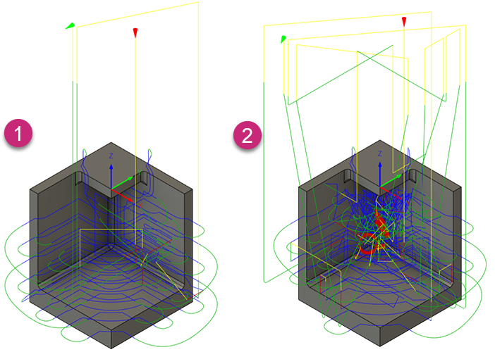
5-axis toolpaths using the Selection (1) and Semi-automatic (2) Primary Modes.