Add a Bar Support structure
Ensure that you have an additive setup with an SLA/DLP or MPBF additive machine selected.
On the Manufacture workspace toolbar, click Additive > Supports > Bar Support
 .
.The Bar Support dialog opens.
With Selection active, on the canvas, click the solid bodies, the faces of solid bodies, or the mesh face groups that you want supported.
Tip: To prevent supports generating at certain areas, select the Avoid checkbox, ensure Avoided Model is active, and then, on the canvas, click the solid bodies, the faces of solid bodies, or the mesh face groups.Enter a Support Overhang Angle between 0 degrees and 90 degrees to specify the angle from the horizontal plane at which supports are needed.
In the General tab, choose an Anchor Density to specify the compactness of the bar supports.

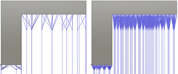
Example of sparse (left) and dense (right) anchors.
In the Bar Properties tab, choose options for Bar Size and Bar Shape to specify how thick the supports are and determine the cross-sectional shape of the supports.

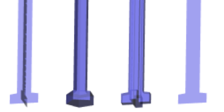
Example of Cross (left), Solid Bar and Single Hatch Tube (center left), Solid Cross (center right), and Hatch (right) bar shapes. A Single Hatch Tube is the same shape as a Solid Bar, but the way the Single Hatch Tube is sliced during export is different.
Optional steps:
To let the bars split into branches in their upper part, on the General tab, select the Bouquets checkbox and choose a Bouquet Density to specify the size of the branching for bouquets.

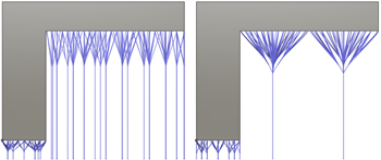
Example of small (left) and large (right) bouquet structures.
To decide where supports should or should not be generated, in the General tab, in the Bars on Supported Model group, select or deselect the checkboxes.
To group supports so they can be tapered and include base plate supports, in the General tab, select the Groups checkbox.
To allow part-to-part supports, in the General tab, deselect the Project Bar to Platform checkbox.
To ensure that bar supports terminate in a right angle at the supported surface, in the Bar Properties tab, select the Right Angle on Part checkbox.
To create support-to-part connections that make the supports easy to break off by hand, in the Connections tab, select the Breakpoint checkbox and choose the Breakpoint Type.
To control how the bar supports connect to the build platform, select the Platform Connection checkbox and choose the Type.

Example of Roots (left), Base Plates for Groups (center), and Platform Connection deselected (right).
To prevent a thickening of the supports at the build platform, in the Connections tab, deselect the Pad on Platform checkbox.
Click OK.
The supports are generated and, in the Browser, under the Supports node, a Bar Support child item is added.
Tip: To reuse these support settings in the future, right-click the child item and choose Store as Template to add it to the Template Library.
If the setup uses an MPBF or eBeam additive machine, you can now generate, and then simulate, the additive toolpath. Otherwise, export the build file.