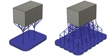
Add a Base Plate Support structure
Ensure that you have an additive setup with an SLA/DLP, MPBF, or binder jetting additive machine selected.
On the Manufacture workspace toolbar, click Additive > Supports > Base Plate Support
 .
.The Base Plate Support dialog opens.
With Selection active, on the canvas, click the solid bodies, the faces of solid bodies, or the mesh face groups that you want supported.
Tip: To prevent supports generating at certain areas, select the Avoid checkbox, ensure Avoided Model is active, and then, on the canvas, click the solid bodies, the faces of solid bodies, or the mesh face groups.(Optional) To enforce a distance between these supports and any other existing supports so that they do not overlap, in the Geometry tab, select the Distance to Other Support checkbox, and then enter a Distance.
In the General tab, choose a Bounding Shape to specify the shape of the base plate in the XY plane.
Enter an Outer Offset (XY Plane) to decide the area that the base plate should cover.
A positive value extends the support beyond the contours of the part while a negative value contracts within.

Example of a 5 mm offset for a base plate support with bar supports (left) and a base plate support with lattice supports (right).
Enter a Height to decide how thick the support is.
Enter a Taper Angle from the bottom to the top of the base plate support.

Example of -60 degrees (left), 0 degrees (center), and 60 degrees (right).
Choose a Pattern Type to determine whether the support is a solid structure, or a structure based on a rectangular or hexagonal design.

Example of Solid (left), Rectangular (center), and Honeycomb (right).
Click OK.
The supports are generated and, in the Browser, under the Supports node, a Base Plate Support child item is added.
Tip: To reuse these support settings in the future, right-click the child item and choose Store as Template to add it to the Template Library.
You can now generate, and then simulate, the additive toolpath.