Add a Setter Support structure
Ensure that you have an additive setup with an FFF, MPBF, SLA/DLP, or binder jetting additive machine selected.
On the Manufacture workspace toolbar, click Additive > Supports > Setter Support
 .
.The Setter Support dialog opens.
With Selection active, on the canvas, click the components, the solid bodies, the faces of solid bodies, or the mesh face groups that you want supported.
Tip: To prevent supports generating at certain areas, select the Avoid checkbox, ensure Avoided Model is active, and then, on the canvas, click the solid bodies, the faces of solid bodies, or the mesh face groups.(Optional) To enforce a distance between these supports and any other existing supports so that they do not overlap, select the Distance to Other Support checkbox, and then enter a Distance.
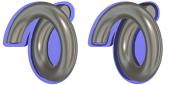
In the General tab, enter a Gap to set the distance between the bodies or components and the support structure.

Example of 1-mm gap (left) and 3-mm gap (right) looking down the XY plane.
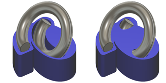
Choose a Z Overlap to decide whether the support structure is or is not generated above the bodies or components.

Example of Remove (left) and Keep (right).
Choose a Bounding Shape to set the shape of the support structure in the XY plane.
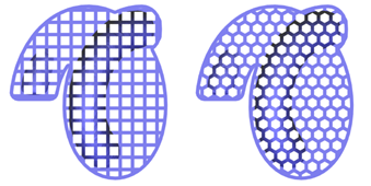
Choose a Pattern Type to decide whether the support is a solid structure, or a structure based on a rectangular, hexagonal, circular, or column design.

Example of Rectangular (left) and Hexagonal (right) patterns looking down the XY plane.
Click OK.
The supports are generated and, in the Browser, under the Supports node, a Setter Support child item is added.
Tip: To reuse these support settings in the future, right-click the child item and choose Store as Template to add it to the Template Library.
If the setup uses an FFF or MPBF additive machine, you can now generate, and then simulate, the additive toolpath. Otherwise, export the build file.