Add a Solid Bar Support structure
Ensure that you have an additive setup with an FFF additive machine selected.
In the Manufacture workspace, click Additive > Supports > Solid Bar Support
 .
.The Solid Bar Support dialog opens.
With Selection active, on the canvas, click the solid bodies, the faces of solid bodies, or the mesh face groups that you want supported.
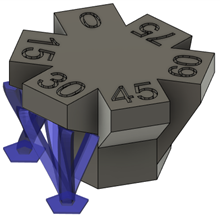
Tip: To prevent supports generating at certain areas, select the Avoid checkbox, ensure Avoided Model is active, and then, on the canvas, click the solid bodies, the faces of solid bodies, or the mesh face groups.Enter a Support Overhang Angle between 0 degrees and 90 degrees to specify the angle from the horizontal plane at which supports are needed.
In the General tab, choose an Anchor Density to specify the compactness of the bar supports.
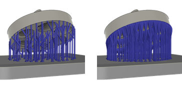
Example of Sparse (left) and Dense (right) anchor densities.
In the Bar Properties tab, enter a Width on Part, Width on Platform, and Bar Shape to specify how thick the supports are and determine the cross-sectional shape.
In the Connections tab, enter a Distance to Part to specify the gap between the support and the surface of the part.
Optional steps:
To specify if supports should be generated on the inside or the outside of the model, in the Geometry tab, select the Advanced Area Filter checkbox, then choose an option for Cluster Inside or Outside.
To enforce a distance between these supports and any other existing supports so that they do not overlap, in the Geometry tab, select the Distance to Other Support checkbox, and then enter a Distance.
To decide where supports should or should not be generated, in the General tab, in the Bars on Supported Model group, select or deselect the checkboxes.
To split the support bars into branches to form a tree-like bouquet structure, in the General tab, select the Bouquets checkbox, then choose a Bouquet Density.
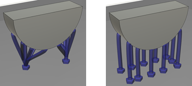
Bouquets selected (left) and Bouquets deselected (right).
To allow bars to form tapered groups, in the General tab, select the Groups checkbox. Adjust the number of bars per group and the group taper.
To provide braces for the bars to limit buckling, in the General tab, select the Brace checkbox.
To force the bar supports to project vertically down, rather than allow them to project at an angle, in the General tab, deselect the Project Bar to Platform checkbox. Note: This reduces the number of bar supports that contact the print bed.
To ensure that bar supports terminate in a right angle at the supported surface, in the Bar Properties tab, select the Right Angle on Part checkbox.
To prevent a thickening of the supports at the print bed, in the Bar Properties tab, deselect the Pad on Platform checkbox.
Click OK.
The supports are generated and, in the Browser, under the Supports node, a Solid Bar Support child item is added.
Tip: To reuse these support settings in the future, right-click the child item and choose Store as Template to add it to the Template Library.
You can now generate, and then simulate, the additive toolpath. Parameters describing how the supports get built are located in the Print Setting Editor.