Work with machine kinematics
Customize and configure the kinematics for your CNC machine definition. Define the relationships between machine components and their movements.
Access a machine's kinematics
On the Manufacture workspace toolbar, on any tab, click Manage > Machine Library
 .
.In the Machine Library, navigate to one of the My Machines subfolders and select the machine definition whose kinematics you want to access.
Click Edit Selected
 .
.In the Machine Definition dialog, select the Kinematics page.
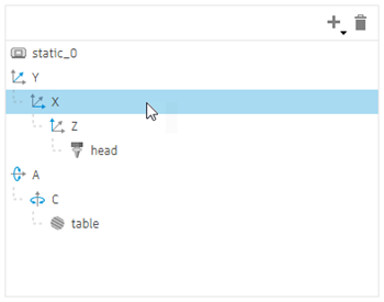
Rearrange the kinematics tree hierarchy
In the kinematics tree, select the desired item.
Click and drag the item to rearrange its position.

Delete a machine item
In the kinematics tree, select the item.
Click Delete
 .
.
Add a machine item
In the kinematics tree, select the item underneath which you want to add the new item.
Click Add
 and then choose the type of item.
Enter a Name for the item.
Configure a linear or rotary axis
In the kinematics tree, select the desired item.
Choose the Coordinate axis type to determine whether the axis is linear (X, Y, Z) or rotary (A, B, C).
Enter a Home Position to define the position to which the axis returns when commanded to home.
Enter the Rapid Feedrate to specify the maximum speed at which the axis can move during rapid moves.
Enter the Max Feedrate to specify the maximum speed at which the axis can move during machining operations.
Choose an Orientation option to define how the axis is aligned in relation to the coordinate system.
For a rotary axis:
Choose a Preference option to determine the preferred direction of rotation for the axis.
(Optional) To ensure that the rotation of the axis is taken into account when calculating the tool center point, and therefore reduce the need for manual adjustments on the machine, select the TCP checkbox.
Choose a Range option to define the range of motion for the axis.
(Optional) Configure advanced settings:
Expand the Advanced Settings group.
Choose a Resolution option to determine whether the axis moves continuously or discretely when machining along curved toolpaths.
If the axis is associated with a sub spindle that is used only for supportive operations, such as positioning the part or tool outside cutting moves or for part transfer, change the Axis Function to Performing Supportive Operations.
For a rotary axis, enter an Offset to set the distance that the tool travels in the X, Y, and Z directions to position the cutter correctly.
For a rotary axis, choose a Reset option to define how the axis’ starting position is handled for new operations and when the axis needs to be rewound and reconfigured because the limit is exceeded.
Configure a head
In the kinematics tree, select the head item.
To indicate that the head holds a rotating spindle for milling operations in a milling machine, select the Spindle checkbox. If the head is used to hold a stationary tool for turning operations in a turn-mill machine, deselect the checkbox.
If the Spindle checkbox is selected, enter a Minimum Speed and a Maximum Speed to set the lowest and highest allowable speed for the cutting tool during milling operations.
Enter a Maximum Tool Length and Maximum Tool Diameter to define the maximum size of tool that the head can handle.
Choose an Orientation option to define how the head is aligned in relation to the coordinate system.
Configure a turret
In the kinematics tree, select the turret item.
Enter the Number of Stations on the turret.
Enter the Number of Attach Points, which is the number of stations that have a tool mounted in place.
To indicate that the turret holds a rotating cutting tool for milling operations in a turn-mill machine, select the Live Tooling checkbox. If the turret is used to hold stationary tools for turning operations in a lathe, deselect the checkbox.
If the Live Tooling checkbox is selected, enter a Minimum Speed and a Maximum Speed to set the lowest and highest allowable speed of the cuting tool during milling operations.
Enter a Maximum Tool Length and Maximum Tool Diameter to define the maximum size of tool that the turret can handle.
Choose an Orientation option to define how the turret is aligned in relation to the coordinate system.
Configure a spindle
In the kinematics tree, select the spindle item.
Enter a Minimum Speed and a Maximum Speed to set the lowest and highest allowable speed of the spindle during turning operations.
Enter the Spindle Power to indicate the maximum power output of the spindle.
Enter the Spindle Peak Torque to indicate the highest rotational force the spindle can achieve.
Enter the Spindle Peak Torque Speed to specify the speed at which the spindle achieves its highest rotational force.
If configuring a sub spindle and the sub spindle's Z axis is in the opposite direction to that of the main spindle's Z axis, select the Reverse Z Axis checkbox.