Drill reference
Manufacture > Milling or Turning > Drill ![]()
Drilling is a common machining task for creating holes in the work piece. This function will usually trigger the CNC controls Canned Cycles. These cycles incorporate the common motion used for a specific hole machining task. There are usually Canned Cycles for basic drilling, deep hole drilling, counter boring, boring and tapping. The canned cycle output in the final code depends on the postprocessor and your machines capabilities.
These are the types of drilling motion that you can perform with this toolpath :
- Drilling - G81 style drilling with rapid out.
- Counterboring - G82 style drilling with dwell at bottom and rapid out.
- Chip breaking - Chip breaking with pecking and partial retracts between pecks.
- Deep drilling - Deep drilling with pecking and full retract between pecks.
- Guided deep drilling - gun drilling - Deep drilling that produces a round hole with a precision diameter. Useful for deep, straight holes in various materials.
- Tapping - Tapping (G84/G74). Synchronous spindle speed and feed.
- Tapping with chip breaking - Tapping with chip breaking.
- Break through - Allows for reduced feed and speed before breaking through a hole.
- Reaming - Reaming (G85 style) with feed out.
- Boring - Boring with dwell at bottom and feed out.
- Stop boring - Boring (G86 style) with spindle stop at the bottom and rapid out.
- Fine boring - Fine boring with shift away from the hole side.
- Back-boring - Boring from the back.
- Circular pocket milling - Circular pocket milling.
- Bore milling - Bore milling.
- Thread milling - Thread milling.
- Probe - Used to measure a feature on the part with a probe tool, or use macros from the machine to define the WCS. Needs special handling in the post processors depending on the machine.
Need more information on these canned cycles?
The input geometry for these cycles can be selected directly from the features of part geometry, and consistent with other 2D operations, input geometry can also be selected from a sketch, (for example: center points of arcs).
When working with solid models, the easiest way to use Drilling is to select the cylindrical faces of the holes. This automatically sets the correct stock height and depth for each hole. Drilling will recognize holes with different starting heights and depths, to create a single drill operation. Notice that when from cylindrical faces, the Select Same Diameter option is available. This allows easy - automatic - selection of any similar holes.
For more information, watch the Spot drilling holes video.
 Tool tab settings
Tool
Press Select to access the tool library.
Feed & Speed
Spindle and Feedrate cutting parameters.
Preset
Populates custom tool's cutting data.
Spindle Speed
The rotational speed of the spindle expressed in Rotations Per Minute (RPM).
Surface Speed
The speed which the material moves past the cutting edge of the tool (SFM or m/min).
Use Feed per Revolution
Changes input of the feedrate to units per spinde's revolution instead of distance over time.
Plunge Feedrate
The drilling feedrate when plunging into stock.
Plunge Feed per Revolution
The plunge feedrate expressed as the feed per revolution.
Retract Feedrate
Feed used when retracting, but not using rapid moves (G0).
Retract Feed per Revolution
The retract feedrate expressed as the feed per revolution.
Coolant
Select the type of coolant used with the machine tool. Not all types will work with all machine postprocessors.
Flute, Shaft & Holder
Specifies how the flute, shaft and holder of the tool is used to avoid collisions with the workpiece.
Shaft and Holder Modes
Specifies how to handle a collision between the shaft or holder and the part when performing cutting moves.
- Detect tool length - The tool is automatically extended further out of the holder to maintain the specified clearances. A message indicating how far the tool is extended appears in the toolpath log.
- Fail on collision - Aborts toolpath calculation when a collision is detected.
- Skip colliding holes - Skips any holes where collisions are detected. The tool moves onto the next available hole that is safe to cut.
Use Shaft and Holder
Enable to include the shaft and holder of the selected tool, in the toolpath calculation, to avoid collisions.
Shaft Clearance
The tool shaft always stays this distance from the workpiece.
Holder Clearance
The tool holder always stays this distance from the workpiece.
Use Flute
Checks for gouges using the tool’s flute length during cutting moves only.
 Multi-Axis tab settings
Machining Type
3-axis - Standard drilling with a fixed Z-axis. Use this for vertical holes aligned with the Z-axis.
4-axis - Define a rotary axis for drilling holes that are not aligned with the Z-axis. Use this for angled holes or holes on sloped surfaces. For more information, check 4-axis machining page.
5-axis - Full 5-axis drilling movements for complex hole geometries. Use this when the tool needs to tilt to access certain areas. You can define axis limits and apply minimum and maximum tilt angles relative to the tool axis. For more information, check 5-axis machining page.
Tool orientation
The tool orientation defines the cutting plane on a part. By default, the Z axis of the work coordinate system (WCS) that is defined in a setup sets the orientation of the tool. You can override the tool orientation set by the WCS using the Tool Orientation group of settings.
For more information, check the Set a tool orientation page.
 Geometry tab settings
Geometry
Allows you to select drilling locations by model face, hole edge, sketch point, sketch circle, or a diameter size range. You can also inherit locations from a previous operation to finish holes that could not be completed in the original operation.
Selection Mode
Specifies which type of selections will be used for finding the drilling locations.
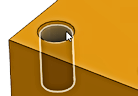
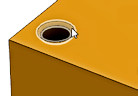
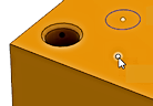
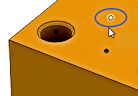
- Faces - This is for Model based feature selection like cylinders or hole chamfers. When selected it provides additional information like the starting height and hole depth. Selected faces is the preferred method for picking drilling locations because it maintains associativity to the Model Feature and will update the drilling operation if the model changes.
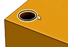
- Points - This is for Geometry based hole selection like hole edges or Sketch geometry. It returns only the XY location and Z starting height of the hole.
- Diameter range - This is for an automatic selection based on a min/max size range of the holes.
- Remaining holes from operation - This is operation-based selection. Creates a fallback operation that automatically selects holes that a primary drilling operation couldn't complete due to collision avoidance. Use this option to create secondary operations that typically use longer tools to reach areas where the primary operation encountered collisions.
| Faces selection - Cylinder | Faces selection - Chamfer | |
 |
 |
|
| Points selection - Hole Edge | Points selection - Sketch Point | Points selection - Sketch Circle |
 |
 |
 |
Hole Faces
Contains the number of faces selected for drilling. This is for Model based feature selection. Use the X to clear all the currently selected items.
Hole Points
Contains the number of points or edge curves selected for drilling. This is for Geometry based hole selection. Use the X to clear all the currently selected items.
Operation
Contains the number of operations selected for fallback drilling. This is for operation-based selection using Remaining holes from operation mode. Use the X to clear all the currently selected items.
Minimum Diameter and Maximum Diameter
Opens a parameter set for creating a minimum and maximum range selection. Eliminates the need to physically select features from the model. The system will evaluate the model based on the Minimum and Maximum Diameter values specified. Use this range to include or exclude hole sizes. This is useful if the part is modeled with sizes that represent different machining processes.
Example: Select all .250 - .2501 diameter holes for drilling and all .2505 - .2506 diameter holes for reaming.
Select Same Diameter
Selects all holes with the same diameter as the currently selected feature.
A single selection will find all matching holes. Using this option is associative to the model. If additional holes with the same diameter are added later, regenerating the operation automatically includes the added holes in the drilling cycle.
Example: If you activate this option, select a single 6mm hole and a single 12mm hole, every 6mm and 12mm hole on the part will automatically be selected.
Check for Occlusions
Deselects any holes of the same diameter that cannot be drilled because of the current tool orientation.
For example, if a hole is on the underside of a part and the drill cannot reach it, the hole is not drilled.
 |
 |
| Deselected | Selected |
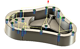
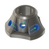
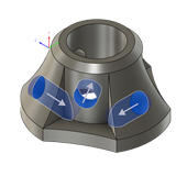
Containment Boundary
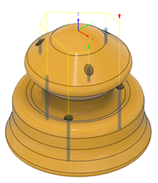
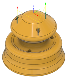
Use this with Select Same Diameter and Diameter Range to include similar items inside the containment areas. Select any Edge or Sketch boundary to contain the drilling locations. Use multiple boundaries or nested boundaries, to include or exclude groups of holes. The toolpath will be inside the selected boundary unless the boundaries are nested. You can nest several boundaries inside each other.
In the examples below, the selected boundaries are shown in blue.
 |
1) Sketch Boundaries 2) Holes inside are included 3) Nested Boundaries 4) Inside areas are excluded |
5) Sketch Boundaries (2) 6) Selecting the rim area only 7) Sketch Boundaries (3) 8) Excluding the rim area |
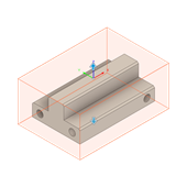
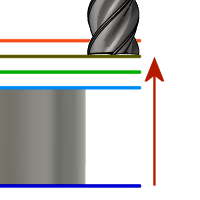
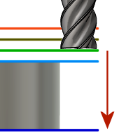
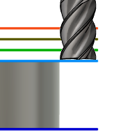
Auto-Merge Hole Segments
Check to merge multiple hole segments. When enable all hole segments are included to determine the starting height for drilling. Use this option when the selected drill hole has a counter bore. This will force the starting height to be at the top of the counter bored hole, rather than the top of the drilled hole.
Example: If a hole was Spot Drilled or Counter Bored first, you may want to start drilling from a clearance above that machined area. Enabling Auto-Merge will start the drilling from above the highest hole segment.
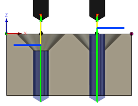 |
Left Side Hole: Auto-Merge Disabled Right Side Hole: Auto-Merge Enabled Blue line indicates the starting height for drilling |
Order by Depth
Changes the order from the highest to lowest, or lowest to highest. Unchecked, the order will start with the holes at the highest Z level and progressively move down. Check to reverse the order.
| Deselected First hole is at the highest Z |
Selected First hole is at the lowest Z |
 |
 |
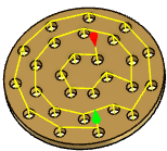
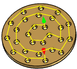
Order
Specifies how the holes should be ordered for machining.
 |
1) Order selected 2) Optimized order 3) Inside to Outside 4) Order by X motion 5) Order by Y motoion |
Reverse Order
Select to change the order of the sorted toolpath.
| Deselected | Selected |
 |
 |
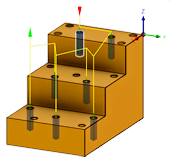
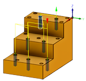
Reset Directions
Reverts all manually fixed through hole directions back to default. Default directions may change automatically to avoid collisions.
| Fixed directions | Default directions |
 |
 |
Avoid/Machine Surfaces
Lets you specify surfaces to machine, avoid, ignore, or mark as fixtures to avoid during toolpath calculation. For more information, check Avoid/machine surfaces page.
 Heights tab settings
Clearance Geometry
Specifies the clearance area type and start location.
Clearance Geometry Type
After completing a cutting move, the tool moves to this safe clearance area before positioning itself for the next cut.
Plane - Standard Z-plane clearance area. The tool moves to a fixed Z height between drilling locations. Use this for 3-axis drilling operations.
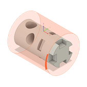
Cylinder - Cylindrical clearance area around a defined axis. The tool moves along the surface of a cylinder between drilling locations. Use this for 4-axis and 5-axis drilling operations on cylindrical parts or when you need clearance around a rotary axis.
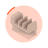
Sphere - Spherical clearance area that provides clearance in all directions. The tool moves within a spherical boundary between drilling locations. Use this for 4-axis and 5-axis drilling operations when you need maximum clearance flexibility or when working with complex part geometries.
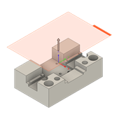
Box - Rectangular clearance area defined by a bounding box. The tool creates linking moves around the perimeter of the workpiece within the box boundaries. Use this for 5-axis machining when you need to control tool movement within a defined rectangular region.
| Plane clearance area | Cylinder clearance area |
 |
 |
| Sphere clearance area | Box clearance area |
 |
 |
Clearance Geometry Direction
Specifies the direction that sets the clearance shape’s orientation in 3D space. Doesn’t change the tool’s orientation.
Rotary axis - Uses rotary axis as a centerline of the cylinder clearance area.
Automatic - Selects the most suitable direction based on the current tool orientation and model geometry.Updates automatically when the tool orientation changes.
Selection - Lets you choose a direction from model geometry, such as a face or an edge.
Setup X axis - Uses X axis of the current setup as the clearance direction.
Setup Y Axis - Uses the Y axis of the current setup as the clearance direction.
Setup Z Axis - Uses the Z axis of the current setup as the clearance direction.
Tool Orientation X Axis - Uses the X axis defined by the Tool Orientation setting. Useful when clearance should align with the tool’s tilt rather than the setup axes.
Tool Orientation Y Axis - Uses the Y axis defined by the Tool Orientation setting. Helpful when a side direction relative to the tool provides safer linking moves.
Tool Orientation Z Axis - Uses the Z axis defined by the Tool Orientation setting. Ideal when “up” follows the tool orientation, such as in angled 3+2 positions.
Direction Selection
Selects an edge to use its normal direction for the clearance direction.
Flip Direction
Reverses the current direction vector of clearance geometry.
Clearance Geometry Origin
Defines the location of the work coordinate system (WCS) origin for spherical and cylindrical clearance area types.
Setup WCS origin - Uses the WCS origin defined in the current setup.
Model origin - Uses the model’s WCS origin.
Selected point - Uses a selected reference to define the WCS origin.
Model box point - Uses a selected point on the model’s bounding box to define the origin.
Stock box point - Uses a selected point on the stock’s bounding box to define the origin.
Origin Selection
Selects a vertex, an edge, or an arc or circle center to set the origin for clearance.
Origin Model Point
Specifies key points on the model’s bounding area to set the WCS origin for clearance. You can choose extremes in X, Y, and Z of the top, center, and bottom of each side.
Origin Stock Point
Specifies key points on the stock’s bounding area to set the WCS origin for clearance. You can choose extremes in X, Y, and Z of the top, center, and bottom of each side.
Clearance Height
The Clearance height is the first height the tool rapids to on its way to the start of the tool path.

Clearance Height.
Clearance Height From
For plane area type:
- Retract height: incremental offset from the Retract Height.
- Feed height: incremental offset from the Feed Height.
- Top height: incremental offset from the Top Height.
- Bottom height: incremental offset from the Bottom Height.
- Model top: incremental offset from the Model Top.
- Model bottom: incremental offset from the Model Bottom.
- Stock top: incremental offset from the Stock Top.
- Stock bottom: incremental offset from the Stock Bottom.
- Hole top: incremental offset from the Hole Top.
- Hole bottom: incremental offset from the Hole Bottom.
- Selection: incremental offset from a Point (vertex), Edge or Face selected on the model.
- Origin (absolute): absolute offset from the Origin that is defined in either the Setup or in Tool Orientation within the specific operation.
For cylinder and sphere area type:
- Retract - Uses the retract height as the clearance height.
- Stock OD - Uses the outer diameter of the stock as the clearance height.
- Model OD - Uses the outer diameter of the model as the clearance height.
- Selection - Uses a selected reference to define the clearance height.
- Radius - Uses a specified radius from the WCS origin as the clearance height.
- Diameter - Uses a specified diameter from the WCS origin as the clearance height.
- Outermost of... - Uses the selected stock, model, or fixture diameter options and applies the largest value as the clearance height.
Clearance Height Select
Selects an edge to use as the reference for the clearance height.
Clearance Height Value
Sets the clearance height using a distance measured from the WCS origin defined in the clearance geometry.
Clearance Height Stock
Controls whether stock diameters or heights are included when determining the clearance height.
Clearance Height Model
Controls whether model diameters or heights are included when determining the clearance height.
Clearance Height Vixture
Controls whether fixture heights from current setup and surface groups are included when determining the retract height.
Clearance Height Offset
Shifts the Clearance Height from the relative position selected in the above drop-down list. You can apply positive or negative offset.
Retract Height
Retract height sets the height that the tool moves up to before the next cutting pass. Retract height should be set above the Feed height and Top. Retract height is used together with the subsequent offset to establish the height.
Retract Height.
Retract Height From
- Clearance height: incremental offset from the Clearance Height.
- Feed height: incremental offset from the Feed Height.
- Top height: incremental offset from the Top Height.
- Bottom height: incremental offset from the Bottom Height.
- Model top: incremental offset from the Model Top.
- Model bottom: incremental offset from the Model Bottom.
- Stock top: incremental offset from the Stock Top.
- Stock bottom: incremental offset from the Stock Bottom.
- Hole top: incremental offset from the Hole Top.
- Hole bottom: incremental offset from the Hole Bottom.
- Selection: incremental offset from a Point (vertex), Edge or Face selected on the model.
- Origin (absolute): absolute offset from the Origin that is defined in either the Setup or in Tool Orientation within the specific operation.
Retract Height Offset
Shifts the Retract Height from the relative position selected in the above drop-down list. You can apply positive or negative offset.
Feed Height
Feed height sets the height that the tool rapids to before changing to the feed/plunge rate to enter the part. Feed height should be set above the Top. A drilling operation uses this height as the initial feed height and the retract peck height. Feed height is used together with the subsequent offset to establish the height.
Feed Height.
Feed Height From
- Clearance height: incremental offset from the Clearance Height.
- Retract height: incremental offset from the Retract Height.
- Disabled: disabling the Feed Height causes the tool to rapid down to the lead-in.
- Top height: incremental offset from the Top Height.
- Bottom height: incremental offset from the Bottom Height.
- Model top: incremental offset from the Model Top.
- Model bottom: incremental offset from the Model Bottom.
- Stock top: incremental offset from the Stock Top.
- Stock bottom: incremental offset from the Stock Bottom.
- Hole top: incremental offset from the Hole Top.
- Hole bottom: incremental offset from the Hole Bottom.
- Selection: incremental offset from a Point (vertex), Edge or Face selected on the model.
- Origin (absolute): absolute offset from the Origin that is defined in either the Setup or in Tool Orientation within the specific operation.
Feed Height Offset
Shifts the Feed Height from the relative position selected in the above drop-down list. You can apply positive or negative offset.
Top Height
Top height sets the height that describes the top of the cut. Top height should be set above the Bottom. Top height is used together with the subsequent offset to establish the height.
Top Height
Top Height From
- Clearance height: incremental offset from the Clearance Height.
- Retract height: incremental offset from the Retract Height.
- Feed height: incremental offset from the Feed Height.
- Bottom height: incremental offset from the Bottom Height.
- Model top: incremental offset from the Model Top.
- Model bottom: incremental offset from the Model Bottom.
- Stock top: incremental offset from the Stock Top.
- Stock bottom: incremental offset from the Stock Bottom.
- Hole top: incremental offset from the Hole Top.
- Hole bottom: incremental offset from the Hole Bottom.
- Selection: incremental offset from a Point (vertex), Edge or Face selected on the model.
- Origin (absolute): absolute offset from the Origin that is defined in either the Setup or in Tool Orientation within the specific operation.
Top Offset
Top Offset is applied and is relative to the Top height selection in the above drop-down list.
Bottom Height
Bottom height determines the final machining height/depth and the lowest depth that the tool descends into the stock. Bottom height needs to be set below the Top. Bottom height is used together with the subsequent offset to establish the height.
 Bottom Heigh.
Bottom Height From
- Clearance height: incremental offset from the Clearance Height.
- Retract height: incremental offset from the Retract Height.
- Feed height: incremental offset from the Feed Height.
- Top height: incremental offset from the Top Height.
- Model top: incremental offset from the Model Top.
- Model bottom: incremental offset from the Model Bottom.
- Stock top: incremental offset from the Stock Top.
- Stock bottom: incremental offset from the Stock Bottom.
- Hole top: incremental offset from the Hole Top.
- Hole bottom: incremental offset from the Hole Bottom.
- Selection: incremental offset from a Point (vertex), Edge or Face selected on the model.
- Origin (absolute): absolute offset from the Origin that is defined in either the Setup or in Tool Orientation within the specific operation.
- To chamfer width: allows the tool to drill just enough to make the chamfer width match the input parameter. The input parameter should not exceed the tool's chamfer width. The calculated height offset is dependent on the tool's parameters (diameter, tip diameter, and tip angle) and on the diameter of the hole. Acceptable selections include cylindrical faces, circles, or arcs.
- To chamfer diameter: the diameter of the new hole is equal to the input parameter. Therefore, the input parameter should not exceed the tool's diameter. The calculated height offset is dependent on the tool's parameters and independent of the hole selection. Acceptable selections include cylindrical faces, circles, or arcs.
Bottom Offset
Bottom Offset is applied and is relative to the Bottom height selection in the above drop-down list.
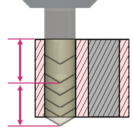
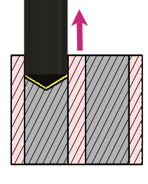
Drill Tip Through Bottom
When Enabled the tool tip will drill past the bottom of the hole. It positions the lip of the drill to the full diameter at the bottom of the hole. It also allows the tool to drill completely through the bottom, or past the bottom using the Break-Through Depth.
 |
Left Side Hole: Depth is to the Tip (unchecked) Right Side Hole: Depth is to the Lip (checked) |
 Cycle tab settings
Cycle Type
The Cycle type is the type of drilling cycle. Fusion provides a number of predefined (canned) drilling cycles.
Selecting a drill cycle determines which parameters can be specified for the drilling operation.
- Drilling - rapid out - Feed in to the programmed depth and rapid out. Used for Center Drilling, Spot Drilling and holes with depths of less than three times the tool diameter.
- Counterboring - dwell and rapid out - Feed in to the programmed depth, dwell for a specified time and rapid out. Used to create a flat bottom on shallow clearance for screws. The dwell improves the finish on the floor of the hole.
- Chip breaking - partial retract - For holes with depths of more than three or four times the tool diameter tool. Uses multiple pecks that periodically retracting the tool to break the chips and/or allow coolant to enter the hole. This is also known as Peck drilling.
- Deep drilling - full retract - Similar to Chip breaking, but retracts the tool completely out of the hole to clear chips and/or flood the hole with coolant. This is also known as Peck drilling.
- Break through - Allows for reduced feed and speed before breaking through a hole.
- Guided deep drilling - gun drilling - A standard gun drill has a single effective cutting edge. This unique head geometry is different from a conventional twist drill. While drilling, guide pads burnish the hole allowing the hole to maintain straightness. The result of this activity is a very round hole with a precision diameter that can also produce deep, straight holes in a variety of materials.
- Tapping - Tapping is a process that cuts threads into a hole, to accept screws. Taps right or left threads in a round hole with a multi-point tool that looks similar to a screw.
- Left tapping - Creates a threaded hole for left handed screws. The tap rotates counterclockwise as it enters the hole and reversed to exit the hole.
- Right tapping - Creates a threaded hole for right handed screws. The tap rotates clockwise as it enters the hole and reversed to exit the hole.
- Tapping with chip breaking - Creates a threaded hole by feeding in and out multiple times, going deeper each time, until it reaches the final depth.
- Reaming - feed out - Feeds in and immediately feeds out after reaching the final depth. This is a precision hole finishing operation.
- Boring - dwell and feed out - Similar to Reaming, but includes a dwell at the bottom depth.
- Stop boring - stop and rapid out - Feeds in to the depth, stops the spindle rotation and rapids out. This does drag the boring insert along the wall during the retract.
- Fine boring - shift Similar to Stop Boring, except that it will orient the tip of the insert and move it away from the wall of the bore before performing the retract move.
- Back-boring - moves to a depth inside the hole and stops, while a reverse counterboring tool is attached. The spindle then starts and the tool feeds up, to counter bore the back side of the part.
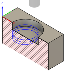
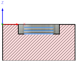
- Circular pocket milling - This can be used to initiate a custom canned cycle on the control for circular pocketing.
- Bore milling - This can be used to initiate a custom canned cycle on the control for helical bor milling.
- Thread milling - This can be used to initiate a custom canned cycle on the control for thread milling.
- Custom - Used to measure a feature on the part with a probe tool, or use macros from the machine to define the WCS. Needs special handling in the post processors depending on the machine. See the more advanced Probing function, under the Setup pull down.
Pecking Depth
Sets the depth for the first peck move, which plunges in and out of the material to clear and break chips.
Pecking Depth Reduction
The amount by which the pecking depth is reduced per peck.
Minimum Pecking Depth
The minimum allowed pecking depth.
Accumulated Pecking Depth
Specifies the pecking depth which forces full retract.
Chip Break Distance
With a chip breaking operation, the drill withdraws a specified distance after advancing into the hole to prevent the binding of chips.
Dwell Before Retract
Enables dwelling before pecking retracts to thin out chips. This can increase tool lift significantly depending on the material being machined.
Dwelling Period
The Dwelling period is the dwelling time in seconds. Specifying a dwell time halts all axis movement for a specified time while the spindle continues revolving at the specified rpm. This can be used to ensure that chips are cleared before retracting from a hole, and will typically improve the finish of a hole.
Typically a dwelling time between 1/4 second and 1 second is sufficient. As an example, specify 0.25 or 1/4 in this field to dwell for 1/4 second.
When post processing a drill cycle, the dwell time is specified as one of the drill cycle parameters (typically P), and in most cases it is output in milliseconds (ms).
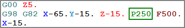
250ms dwell time in G82
When posting using expanded cycles, the dwell time is output as a regular dwell command (G4).
To calculate the minimum dwell time that will ensure at least one complete revolution, use a value of 60 divided by the spindle speed. As an example, at 350 RPM the minimum dwell time should be 60 / 350 = 0.171s (which could be rounded to 0.2s).
Break Thorugh Distance
Specifies the distance above the bottom of the hole depth, where the cycle should adjust feed and speed, before breaking through the bottom. This value is measured up from the bottom of the hole.
Can be used for any material that might chip or crack as the tool breaks through the bottom of the hole.
Break Through Feedrate
Controls the feedrate to apply, when the Break Through Distance is reached. This can be increased or decreased depending on the characteristics of the material being drilled.
Break Through Feed per Revolution
Input uses units per spinde's revolution instead of distance over time.
Break Through Spindle Speed
Controls the spindle speed to apply, when the Break Through Distance is reached. This can be increased or decreased depending on the characteristics of the material being drilled.
Starting Depth
Because of the excessive length of a Gun Drill, a pilot hole is generally drilled, to keep b the tool from walking off of the true hole position. This value specifies the positioning depth inside the pilot hole. This positioning move is made in feed mode and an independent feedrate can be specified when moving to this depth.
Dwelling Depth
Specifies the depth below the stock to dwell. This can be used to clear chips for through-holes before retracting. This is not implemented in all cycles, for all postprocessors.
Stop Spindle
Select to stop the spindle before and after the operation. The spindle will start once the tool reaches the Starting Depth of the pilot hole.
Positioning Spindle Speed
Specifies the spindle speed to use when positioning to the Starting Depth.
This can be different from the cutting spindle speed. You may want to use a lower speed for safety when positioning into a pilot hole, or match the cutting speed for consistency.
Positioning Feedrate
Specifies the feedrate to use when positioning to the Starting Depth.
This can be greater than the cutting feedrate to save time, or less than the cutting feedrate for safety reasons.
Positioning Feed per revolution
Input uses units per spinde's revolution instead of distance over time.
Pecking Depth
Specifies the increment to drill, breaking the full depth into multiple increments.
Sets the depth for the first peck move, which feeds in and rapids out of the hole to remove and break chips. Peck Depth Amount
Pecking Depth Reduction
Specifies the amount to subtract from the Pecking Depth, for each subsequent peck. Reduces the load on the drill, as the depth increases. Multiple Pecks Shown with a 2mm Reduction
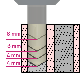
Example: Peck Depth of 8mm, a Pecking Depth Reduction of 2mm and a Minimum Pecking Depth of 4mm. The first peck will be 8mm. The second peck will be 6mm. The third peck will be 4mm.
A value of 0.0 maintains the same Pecking Depth for all moves, until the full depth is reached.
Accumulated Pecking Depth
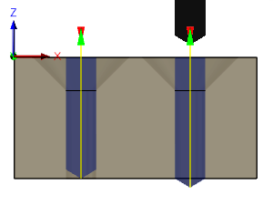
Specifies the the total depth to drill, before the tool retracts to the Feed Height. This will extract the chips from the hole and allow coolant to enter the hole.
Total distance to peck before making a full retract.
Example: Pecking Depth of 8mm and an Accumulated Pecking Depth of 14mm, the cycle will complete 2 pecks before retracting to the Feed Height.
Chip Break Distance
Specifies how much the tool will retract between pecks. This minimal clearance retract breaks the chip and relieves pressure on the tool tip between pecks. Shown in yellow.
Chip Break Retract Shown in yellow.
Example: Pecking Depth of 8mm, an Accumulated Pecking Depth of 14mm and a Chip Breaking Distance of .50mm. The cycle will complete the first peck, retract .50mm and then proceed with the next peck.
Incremental Depth
Specifies the Z depth for each XY Circular Pocket pass. An Incremental Depth of 2mm on a pocket that is 6mm deep, will create 3 Z level passes.
| Incremental Depth of 2mm on a 6 mm deep pocket | 3 depth cuts |
 |
 |
Cycle Direction
Specifies the cut direction as a Climb or Conventional cut.
Climb - The tool advances so that the cutting flutes engage the material at maximum thickness and then decrease to zero. This method produces less cutting pressure and heat, leaves a better surface finish, and results in longer tool life. Climb milling is generally recommended for CNC machines.
Conventional - The tool cuts in the opposite direction, causing it to start at zero thickness and increase to maximum. This method causes the tool to rub against the cutting surface, which can work-harden the material, generate heat, and increase tool wear. Conventional milling is typically used only when specifically recommended by the tool manufacturer for certain materials.
Use Hole Diameter
Specifies whether we drill to hole diameter or to a set value.
Stepover
Specifies the distance between cuts in the XY plane.
Rather than push the tool in a linear move in XY, the stepover is created by shifting the arc center, until the full diameter size is achieved.
Repeat Pass
Repeat Pass Select to create an additional finish pass at the final depth.
This could be called a spring pass, to remove deflection from the cutting tool and create a smoother finish on the bottom.
Stock to Leave
The amount of stock left for subsequent roughing or finishing operations.
Radial Stock to Leave
The radial stock to leave parameter controls the amount of material to leave in the radial (perpendicular to the tool axis) direction, that is, at the side of the tool.
Pitch
Specifies the distance to step in Z while creating the helical pass around the contour.
Use Multiple Steps
Select to create multiple XY steps for the cut.
Threading
Select the direction of the thread milling cycle, to create right- or left-handed threads.
Cycle Diameter
Specifies the final diameter of the Circular Bore.