Drilling Cycles reference
Drilling Cycles are also referred to as Canned Cycles because a single line of code can combine all the motion required for a hole machining task. This reduces the program size and makes it easier to change the drilling requirements at the machine.
Not all CNC controllers have the same canned cycles. Most machines will have canned cycles for common hole functions like Center/Spot Drilling, Peck Drilling, Counter Boring, Boring, Reaming and Tapping. Some machines will have more specialized cycles like Gun Drilling and Back Boring. Fusion uses the post processor to pass parameters to your machines built-in canned cycles. If your machine does not have a specific canned cycle, Fusion will output the axis positioning moves in a long-hand code format. If you are getting long-hand code moves, you may actually gain additional Fusion functionality that is not available in your canned cycle. If you know your machine has a canned cycle for the function you selected and you are getting long-hand code, you can contact someone at the Marketplace about having your post processor customized.
This is a list of the Fusion Drilling Cycles and the type of motion they produce. For the sake of simplicity, we will refer to these cycles using the common G-Code and the common alpha numeric codes, used to define the cycle. A typical canned drilling cycle uses a G80 series code. Some will use a G70 series code. These descriptions are generic and do not apply to all CNC machines.
The general canned cycle structure will look something like this:
G8# X(position) Y(position) Z(depth) R(retract height) Q(incremental peck amount) P(dwell time) F(feedrate)
Drilling - G81 is commonly used for spot drilling and basic drilling in softer materials, where the hole depth is less than 3x the diameter.
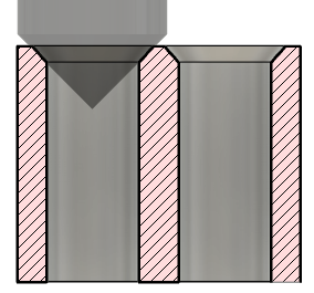 |
G81 Drilling Motion: Positions to the retract height or "R plane" (R) Feeds (F) to the depth (Z) Rapids out to the retract height (R) |
Counterboring - G82 is commonly used for counter boring holes, since the dwell at the final depth polishes the bottom of the hole for a flat surface.
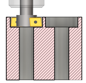 |
G82 Counter Boring Motion: Positions to the retract height or "R plane" (R) Feeds (F) to the depth (Z) dwells for a time (P) Rapids out to the retract height (R) |
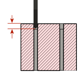
Chip breaking - G73 is commonly used for drilling deep holes when the tool is pulling up long stringing chips. After drilling into the hole, the tool retracts a small distance, then continues drilling further for the next increment. This continues until the full depth is reached. These small retracts will break any long chips created by the drill.
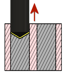 |
G73 Chip Breaking Motion: Positions to the retract height or "R plane" (R) Feeds (F) into the hole an incremental distance (Q) Retracts a small distance (shown in yellow) Continues the incremental pecks (Q) and retracts until the final depth (Z) is reached Rapids out to the retract height (R) |
Peck Drilling - G83 is commonly used for drilling deep holes when the chips need to be pulled out of the hole. After drilling into the hole, the tool retracts to the R Plane, pulling out the chips and allowing coolant to enter the hole. The drill then returns to where it left off and continues drilling further for the next increment. Sometimes there is a parameter to reduce the peck amount as the tool gets deeper into the hole. This continues until the full depth is reached.
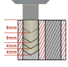 |
G83 Peck Drilling Motion: Positions to the retract height or "R plane" (R) Feeds (F) into the hole an incremental distance (Q) Retracts to the "R plane" (R) Rapids back in to where it left off Continues the incremental pecks (Q) and retracts until the final depth (Z) is reached Rapids out to the retract height (R) |
Guided Deep Driling / Gun Drilling - A specialized cycle used for drilling deep holes when the depth is greater than 20x the diameter of the hole. Most CNC machines do not have gun drilling canned cycles. Gun Drilling generally requires a short pilot hole drilled into the part, to keep the extremely long drill from drifting off of the location. The drill itself may also have guides along the diameter that match the cutting tip diameter. This keeps the tool rigid in the hole. Gun Drills commonly use through-the-tool pressurized coolant to force the chips out and keep the cutting tip lubricated. After feeding into the pilot hole, the gun drill will feed all the way to the final depth before retract out of the hole, to the R plane.
 |
Gun Drilling Motion: Positions to the retract height or "R plane" Feeds into the pilot hole (shown in the diagram) Drills until the final depth is reached Rapids out to the retract height |
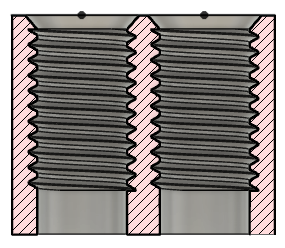
Tapping - The purpose of Tapping is to cut spiral grooves into the inside diameter of a cylinder. It commonly uses G84 (right handed) and G74 (left handed) canned cycles. A Tap is a tool that looks very much like a screw, except the threads are sharp for cutting the material. Tapping, feeds into the hole at a rate that matches the thread pitch and requires a synchronized spindle RPM. When it reaches the final depth, the spindle will reverse direction and feed out of the hole at the same feedrate. It essentially screws the tool in, reverses the spindle and screws the tool out.
Fusion has several options for tapping. You should create a sample toolpath operation for each and compare the output to the samples in your machines programming manual. This is a basic description for each Tapping Cycle and they all require synchronous spindle speed and feedrate.
- Tapping - Tapping Right or Left handed threads (G84/G74). Spindle direction is determined by the settings in the tool library.
- Tapping Left Handed - Tapping specific for left handed threading tools.
- Tapping Right Handed - Tapping specific for right handed threading tools.
- Tapping with chip breaking - Tapping with chip breaking. Screws the tool in a partial distance, reverses to break the chip, and then repeats the process until the final depth is reached.
 |
 |
|
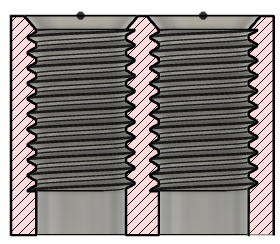
| Right handed tapped holes | Left handed tapped holes |
Break Through - A more specialized type of hole operation. Break Through allows for a reduced feed and speed right before breaking through the bottom of the hole. This might be used for brittle materials where the force of breaking through, chips the bottom of the hole.
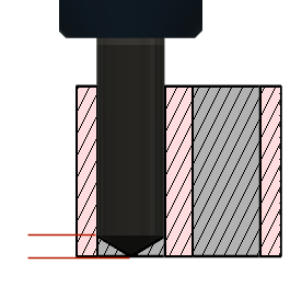 |
Break Through Motion: Positions to the retract height or "R plane" (R) Feeds (F) into the hole Before reaching the final depth (shown in red) it reduces the feedrate Drilling continues to the final depth Rapids out to the retract height |
Reaming - G85 is commonly used for reaming holes to a precision diameter.
 |
G85 Reaming Motion: Positions to the retract height or "R plane" (R) Feeds (F) to the depth (Z) Feeds out to the retract height (R) |
Boring - G89 is commonly used for boring flat bottom holes to a precision diameter. The dwell at the final depth polishes the bottom of the hole for a flat surface, then the tool feeds out to the R plane.
 |
G89 Boring Motion: Positions to the retract height or "R plane" (R) Feeds (F) to the depth (Z) Dwells at the bottom (P) Feeds out to the retract height (R) |
Boring with Spindle Stop - G86 is commonly used for boring flat bottom holes to a precision diameter. The spindle stops at the final depth of the hole, then the tool rapids out to the R plane.
 |
G86 Boring with Spindle Stop Motion: Positions to the retract height or "R plane" (R) Feeds (F) to the depth (Z) Stops the spindle at the bottom Rapids out to the retract height (R) |
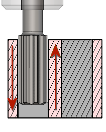
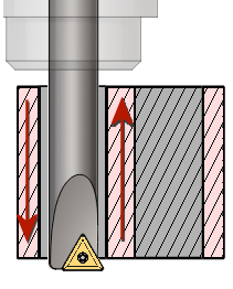
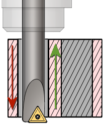
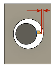
Fine Boring (shift) - G76 is commonly used for boring holes to a precision diameter by only machining in one direction. The spindle stops at the final depth of the hole, in some cases the tool tip might be oriented to a specific position, the tool shifts away from the face of the bore and then the tool rapids out to the R plane.
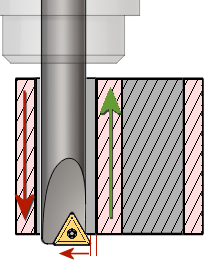 |
G76 Fine Bore Motion: Positions to the retract height or "R plane" (R) Feeds (F) to the depth (Z) Stops the spindle at the bottom Possibly does a spindle orientation move Shifts the tool away from the bore wall (Q) Rapids out to the retract height (R) |
 |
Back Boring (shift) - G87 is commonly used to chamfer, bore or counter bore holes from the back side of the part. This cycle may work in a several different ways.
Using a reverse chamfer tool, similar to a boring bar with a cutting surface on the upper side of its base. The insert on these tools are sometimes extended with the centrifugal force, as the spindle turns. Stopping the spindle retract the insert.
Using an L-shaped tool placed in the spindle with a cutting surface on the upper side of its base. You stick it carefully through the hole when it is not spinning, oriented so it fits through the hole, then you position the center line of the tool with the center line of the hole, start the spindle and feed the tool upward to make the counterbore. Once completed, you stop the tool, shift off of the center line and retract it out of the hole.
Using a blank tool shaft, the tool rapids into the full depth of the hole where it stops, so a reverse counter bore tool, with a quick disconnect, can be mounted. The tool feeds up to machine the counter bore, moves down off the surface and then stops the spindle so the counter bore can be removed, before the shaft retract out of the hole.
Because of the complexity of the motion and the amount of manual intervention required, this type of operation is rarely used.
 |
G87 Back Boring Motion: Positions to the retract height or "R plane" (R) Rapids to the depth Dwells at the bottom (P) The reverse counter bore tool is attached to the tool shaft The tool feeds to the counter bore depth The tool moves off of the surface The counter bor is removed The tool rapids out to the retract height (R) |
Circular Pocket Milling - Fusion uses this cycle to pass parameters to the pocket milling cycle on your machine control. Visually, there is no display in Fusion to show you any pocket milling. The 2D Adaptive or 2D Circular milling toolpaths will certainly do a better job of machining the pocket, than the canned pocket cycle in your CNC controller. But the advantage of the canned cycle is the reduced program size. A single line of canned cycle code can clear the same pocket that might be 40 lines of code, using the 2D Adaptive or 2D Circular. Another advantage is the ability to make adjustments to the size or cutting steps of the circular pocket, at the machine.
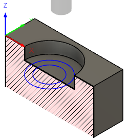 |
Circular Pocket Milling Motion: Positions to the retract height or "R plane" (R) Calls the canned cycle No toolpath will be displayed in Fusion |
Bore Milling - Fusion uses this cycle to pass parameters to the bore milling cycle on your machine control. Visually, there is no display in Fusion to show you any bore milling. The 2D Adaptive or 2D Bore milling toolpaths will certainly do a better job of machining the bore, than the canned bore cycle in your CNC controller. But the advantage of the canned cycle is the reduced program size. A single line of canned cycle code can clear the same bore that might be 40 lines of code, using the 2D Adaptive or 2D Bore. Another advantage is the ability to make adjustments to the size or cutting steps of the bore, at the machine.
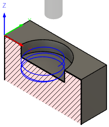 |
Bore Milling Motion: Positions to the retract height or "R plane" (R) Calls the canned cycle No toolpath will be displayed in Fusion |
Thread Milling - Fusion uses this cycle to pass parameters to the thread milling cycle on your machine control. Visually, there is no display in Fusion to show you any bore milling. The 2D Thread Milling toolpath will certainly do a better job of machining the threads, than the canned threading cycle in your CNC controller. But the advantage of the canned cycle is the reduced program size. A single line of canned cycle code can machine the same threads that might be 40 lines of code, using the 2D Threading. Another advantage is the ability to make adjustments to the size or cutting steps of the threads, at the machine.
|
Thread Milling Motion: Positions to the retract height or "R plane" (R) Calls the canned cycle No toolpath will be displayed in Fusion |
Custom - Fusion uses this cycle to pass parameters to the probing cycle on your machine control. Visually, there is no display in Fusion to show you any probing motion. The Inspection tools in Fusion offer more options for probing and visual feedback of the probing process. They will certainly do a better job, if probing is needed.
| Probing Motion: Positions to the retract height or "R plane" (R) Calls the canned cycle No motion will be displayed in Fusion |