Document Settings reference (Drawing workspace)
In the Document Settings dialog, you can view or change standard, units, text, dimension, line type, width and color settings for the current drawing in the Drawing workspace in Fusion.
If you plan to reuse title blocks, borders, document settings, or sheet settings across multiple drawings, create a drawing template to save time and apply consistent standards. You can also create placeholder views and placeholder tables that automatically generate drawing views and part lists from the referenced design when you use the template to create a new drawing.
When you create a new drawing using the From Scratch option, default document settings are based on the preferences you set in the Fusion Preferences dialog.
Access the Document Settings dialog
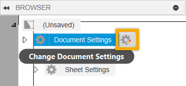
In the browser, hover over the Document Settings node, then click the icon Change Document Settings next to it, and the Document Settings dialog displays.
Tabs
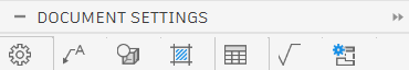
The Document Settings dialog options are organized into tabs.
- Document Settings Tab
- Annotation Tab
- View Tab
- Hatch Tab
- Table Tab
- Symbol Tab
- View Details Tab
Document Settings Tab 
Lets you view or change standard, units, text, line width and revision history settings.
Some document settings are read-only, because they're inherited from the design, controlled by the drafting standard, or can only be specified when you first create a drawing.
Standard (read-only)
Displays the drafting standard specified when the drawing was created.
- ISO
- ASME
Units (read-only)
Displays the units specified when the drawing was created.
- Millimeters (mm)
- Inches (in)
Projection Angle (read-only)
Displays the projection angle.
- First Angle (ISO)
- Third Angle (ASME)
Delimiter
Lets you choose a comma or full stop to specify the decimal delimiter of a number.
- Decimal
- Comma
Text
Contains all settings related to font and text heights within the current document.
Font
Select a font for text and dimensions from the dropdown menu.
Text Height Group
From the dropdown menu, select a text height for notes, leader notes, hole and thread notes, bend notes, dimensions, symbols, tables, parts lists and balloons.
For units in millimeters:
| Text Height Group | Small Text Height | Medium Text Height | Large Text Height |
|---|---|---|---|
| Small | 1.8mm | 2.5mm | 3.5mm |
| Medium | 2.5mm | 3.5mm | 5mm |
| Large | 3.5mm | 5mm | 7mm |
| Custom | Lets you set a text height for each group separately. You can type in any positive value. |
For units in inches:
| Text Height Group | Small Text Height | Medium Text Height | Large Text Height |
|---|---|---|---|
| Small | 0.07in | 0.1in | 0.12in |
| Medium | 0.1in | 0.12in | 0.24in |
| Large | 0.12in | 0.24in | 0.35in |
| Custom | Lets you set a text height for each group separately. You can type in any positive value. |
Small Text Height
Displays the Small Text Height value. Select Custom to specify a text height other than the default.
Medium Text Height
Displays the Medium Text Height value. Select Custom to specify a text height other than the default.
Large Text Height
Displays the Large Text Height value. Select Custom to specify a text height other than the default.
Units
Units
Select primary dimension units from the dropdown menu.
- Centimeters (cm)
- Millimeters (mm)
- Meters (m)
- Inches (in)
- Feet (ft)
Format (Only for Inches and Feet)
Select a format for dimensions from the dropdown menu.
- Decimal: Can be represented as an inch, meter, millimeter, or any other unit.
- Fractional: The unitless decimal units, which display the value in fractions rather than decimals.
- Engineering: Same as the architectural units, but they represent the feet and inches in the format of the decimal.
- Architectural: The architectural units are based on the feet and inches. It uses fractions to represents the partial inches. It displays feet and inches in the format of decimals and fractions.
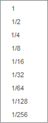
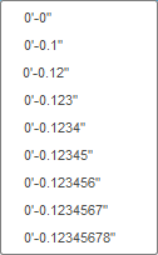
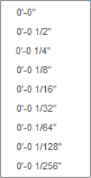
Linear Precision
Select a precision for linear dimensions from the dropdown menu.
Linear Precision is based on the Units and Unit Format.
| Decimal | Fractional | Engineering | Architectural |
|---|---|---|---|
 |
 |
 |
 |
Angular Precision
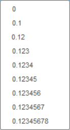
Select a precision for angular dimensions from the dropdown menu.
- 0
- 0.1
- 0.12
- 0.123
- 0.1234
- 0.12345
- 0.123456
- 0.1234567
- 0.12345678
Zeros/Units
- Leading Zeros

Select to display leading zeros in dimensions.
- Trailing Zeros

Select to display trailing zeros in dimensions.
- Unit Abbreviation


Select to display units in dimensions.
Alternate Units
Units
Select primary dimension units from the dropdown menu.
- Centimeters (cm)
- Millimeters (mm)
- Meters (m)
- Inches (in)
- Feet (ft)
Format (Only for Inches and Feet)
Select a format for dimensions from the dropdown menu.
- Decimal: Can be represented as an inch, meter, millimeter, or any other unit.
- Fractional: The unitless decimal units, which display the value in fractions rather than decimals.
- Engineering: Same as the architectural units, but they represent the feet and inches in the format of the decimal.
- Architectural: Based on the feet and inches. It uses fractions to represents the partial inches. It displays feet and inches in the format of decimals and fractions.
Linear Precision
Select a precision for linear dimensions from the dropdown menu.
Linear Precision is based on the Units and Unit Format.
| Decimal | Fractional | Engineering | Architectural |
|---|---|---|---|
|
|
|
|
Zeros/Units
- Leading Zeros
Select to display leading zeros in dimensions.
- Trailing Zeros
Select to display trailing zeros in dimensions.
- Unit Abbreviation
Select to display units in dimensions.
Mass
Select the Mass Units for title block and parts list from the dropdown menu.
- Use Model Settings
- grams (g)
- kilograms (kg)
- ouncemass
- lbmass
Mass Precision
Select the Mass Precision for title block and parts list from the dropdown menu.
- Use Model Settings
- 0
- 0.1
- 0.12
- 0.123
- 0.1234
- 0.12345
- 0.123456
- 0.1234567
- 0.12345678
Line Widths
Contains all settings related to Line Widths.
Line Width Group
Select a Line Width Group from the dropdown menu.
| Line Width Group | Thin Line Width | Medium Line Width | Thick Line Width |
|---|---|---|---|
| Very Thin | 0.13mm | 0.18mm | 0.25mm |
| Thin | 0.18mm | 0.25mm | 0.35mm |
| Medium | 0.25mm | 0.35mm | 0.5mm |
| Thick | 0.35mm | 0.5mm | 0.7mm |
| Very Thick | 0.5mm | 0.7mm | 1.0mm |
| Custom | Lets you set a line width for each group separately. |
The following list of line widths is available when you select the Custom option.
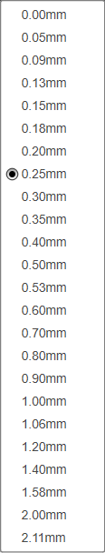
Thin Line Width
Displays the Thin Line Width value in mm. Select Custom to specify a line width other than the default.
Medium Line Width
Displays the Medium Line Width value in mm. Select Custom to specify a line width other than the default.
Thick Line Width
Displays the Thick Line Width value in mm. Select Custom to specify a line width other than the default.
Display Line Widths
Check the box to display line widths on the sheet in the Fusion canvas.
Line Type Scale
Controls the scale and appearance of dashed lines in the drawing.
Revision History
Contains all settings related to Revision History.
Revision Scope
Select the Revision Scope for your drawing.
- Drawing: Allows you to add the same Revision History table to each sheet of your drawing if needed.
- Sheet: Allows you to modify the Revision History table on each sheet so that each sheet of your drawing has a different Revision History table if needed.
Numbering
Select the Numbering style for your drawing.
- Custom
- A,B,C
- 1,2,3
Standards
Displays the standard revisions used by Surface Texture, Feature Control Frame, Datum Identifiers, Welding, and Taper and Slope symbols. The standard revisions displayed by each symbol follow the document's main Standard settings.
Surface Texture (read-only)
Displays the standard revision used by surface texture symbols.
- ISO 1302:2002(E) (ISO)
- ASME Y14.36M - 1996 (ASME)
Feature Control Frame (read-only)
Displays the standard revision used by feature control frame symbols.
- ISO 1101:2012(E) (ISO)
- ASME Y14.5M - 1994 (ASME)
Datum Identifier (read-only)
Displays the standard revision used by datum identifier symbols.
- ISO 1101:2012(E), ISO 5459:2011(E) (ISO)
- ASME Y14.5M - 1994 (ASME)
Welding (read-only for ISO)
Displays the standard revision used by welding symbols.
- ISO 2553:2019, ISO 4063:2009 (ISO)
- ANSVAWS A2.4 - 2012 (ASME)
- ANSVAWS A2.4 - 1998 (ASME)
Taper and Slope (read-only)
Displays the standard revision used by taper and slope symbols.
- ISO 3040:2009(E) (ISO)
- ASME Y14.5M - 1994 (ASME)
Edge Symbol (read-only)
Displays the standard revision used by edge symbols.
- ISO 13715:2000
Annotation, View, Hatch, Table, and Symbol Tabs
Let you view or change line type, line width, color, gap, and arrowhead settings.
Line Type
Select the Line Type from the dropdown.
- CENTER
- CENTER2
- Continuous
- HIDDEN
- HIDDEN2
- PHANTOM
Line Width
Select the Line Width from the dropdown.
- Thin
- Medium
- Thick
Color
Select the color from the color picker.
Gap Distance (Only in the Annotation Tab)
Lets you type in a specific gap distance value for the dimension lines as they come off of the objects you are dimensioning.
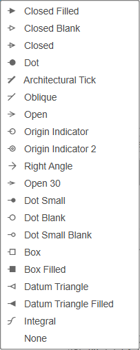
Arrowhead
Select the arrowhead type for dimensions, leaders, balloons, bend IDs, and hole IDs. Mix and match arrowhead types to create the desired look.
The tables below show the object properties you can change, as well as their order within the each Tab.
Annotation Tab 
| Object Name | Line Type | Line Width | Color | Gap | Arrowhead |
|---|---|---|---|---|---|
| Dimensions | |||||
| All Dimensions | |||||
| Edge Extensions | |||||
| Labels | |||||
| Bend IDs | |||||
| Hole IDs | |||||
| View Label | |||||
| Notes | |||||
| Bend Notes | |||||
| Hole and Thread Notes | |||||
| Leader Notes | |||||
| Sketches | |||||
| Model Sketches |
View Tab 
| Object Name | Line Type | Line Width | Color |
|---|---|---|---|
| Visible Outer Lines | |||
| Tangent Edges | |||
| Hidden Lines | |||
| Center Lines and Marks | |||
| Bend Centers | |||
| More Options | |||
| Detail Boundaries | |||
| Section Lines | |||
| Tweak Trails | |||
| Broken View Breaks | |||
| Hidden Lines (narrow) |
The Display Section Line checkbox (only for ISO) gives you the option to display or hide section lines.
Hatch Tab 
| Object Name | Line Type | Line Width | Color |
|---|---|---|---|
| Hatch |
Table Tab 
| Object Name | Line Type | Line Width | Color | Arrowhead |
|---|---|---|---|---|
| General | ||||
| Custom Tables | ||||
| Parts List | ||||
| Balloons | ||||
| Hole Table | ||||
| Hole Table Origin | ||||
| Revision History Table | ||||
| Revision Marker | ||||
| Revision Cloud | ||||
| Bend Table |
Symbol Tab 
| Object Name | Line Type | Line Width | Color |
|---|---|---|---|
| Symbols |
Majority Symbol Types:
 Full List: Placed as a Majority symbol. Displays all edge conditions, including exceptions.
 Simplified List: Placed as a Majority symbol. Groups identical edge conditions.
View Defaults Tab 
Lets you view or change all default settings.
Drawing View Defaults
Contains all default settings.
Type
- Assembly
- Animation
- Component
- Sheet Metal: Folded
- Sheet Metal: Flat Pattern
Style
Select the view style for the selected drawing view.
- Visible Edges
- Visible Edges and Hidden Edges
- Shaded
- Shaded with Hidden Edges
Edge Visibility
Adjust the Tangent Edges, Interference Edges, and Thread Edges settings.
Tangent Edges
Select a display style for tangent edges.
- Full Length
- Shortened
- Off
Interference Edges
Check to display edges where components intersect.
Thread Edges
Check to display threads on threaded edges.
Automated Center Marks and Center Lines
Automatically create center lines and center marks for all holes in a view.
Center Marks
Choose the hole types that receive automated center marks.
- Hole: Creates a center mark for hole features.
- Round Extrudes: Creates a center mark for round extrudes.
- Round Cuts: Creates a center mark for round cuts.
- Pattern: Creates a center mark patterns for circular holes.
- Fillet: Creates a center mark for fillets.
Minimum fillet radius (Fillet only)
Specify the minimum fillet radius for a center mark to be created.
Maximum fillet radius (Fillet only)
Specify the maximum fillet radius for a center mark to be created.
Center Lines
Choose the hole types that receive automated center lines.
- Hole: Creates a center line for hole features.
- Round Extrudes: Creates a center line for round extrudes.
- Round Cuts: Creates a center line for round cuts.