Activity 1: Placing components
In this activity, you place components necessary to make the electronic component. This is needed to start a Schematic of a PCB for a double LED flasher.
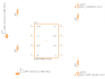
Components added in the Schematic design.
Steps
Confirm that the Tutorial-Fusion library added and enabled in the new schematic design.
Confirm that the grid size is 0.1 inches.
Click Design > View > Grid Settings
 .
.Confirm that the Size is 0.1 inch or equivalent.
Click Cancel if no changes were made, or OK if changes were made.
Note: It is strongly recommended to work on 0.1 inches or equivalent grid size to have proper connection of nets.
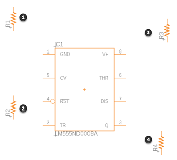
Add the timer, LM555N to the schematic.
Click Design > Place > Place Component

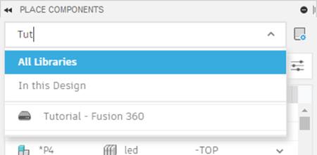
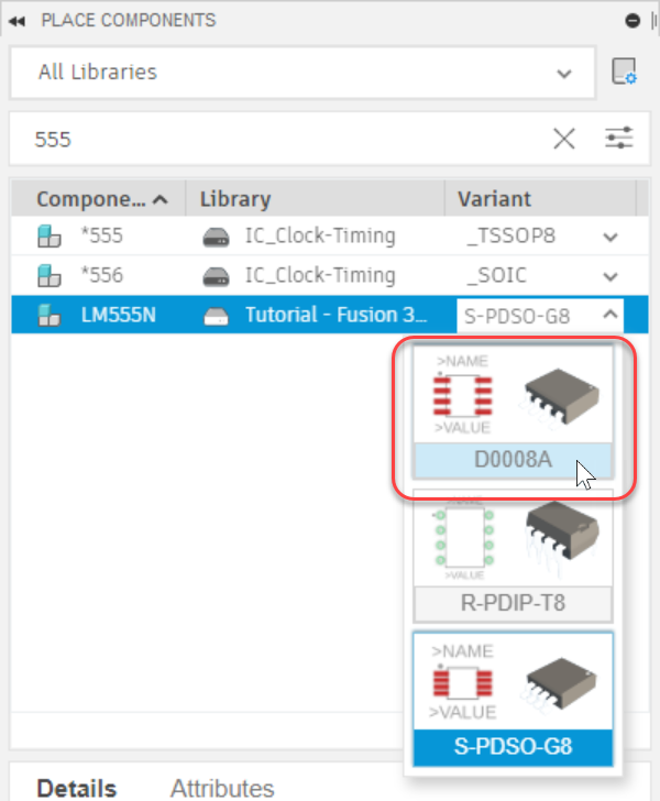
Enter 555 into the Filter search box.
In the Tutorial-Fusion Library, click the arrow next to LM555N to expand the list of variants.
Select the D0008A variant.
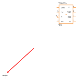
Double-click or drag and drop the LM555N component from the Place Components panel into the canvas. Using Enter will also put you in placement mode.
Properly orient the component using the controls in the Add dialog or by:
- Right-click twice to rotate the component 180 degrees.
- Clicking the mouse wheel once to mirror the component.
Note: Don't worry if you don't like the position of the component added. The position will be adjusted later.Locate the origin symbol on the screen and place the component in the positive coordinate space. It is recommended to place all components in the positive coordinate space.
Click Done or press Esc to exit placement mode and return to the Place Component panel.
Place four R-US_CHIP-0805 resistors to the schematic.
Clear the contents of the Search box and enter R-US.
Click the variant drop-down list and select CHIP-0805, then double-click the row and move the pointer on the canvas.
Right-click to rotate the resistor symbol 90 degrees.
Position the four resistors in the locations shown in the image below.
Click Done or press Esc to exit placement mode and return to the Place Components panel.
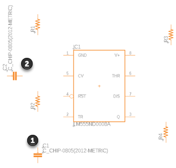
Add two C-CHIP-0805 capacitors to the schematic.
In the Tutorial-Fusion library locate the C component.
Select CHIP-0805(2012-METRIC) from variant drop-down list.
Double-click the row and move the pointer on the canvas.
Position two capacitors in the locations shown in the image below.
Click Done or press Esc to exit placement mode and return to the Place Components panel.
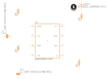
Add one LED_CHIP RED-2012 LED to the schematic.
In the Tutorial-Fusion library locate the LED_CHIP component.
Select RED-2012 from variant drop-down list.
Double-click the row and move the pointer on the canvas.
Position the LED in the location shown in the image below.
Click Done or press Esc to exit and return to the Place Components panel.
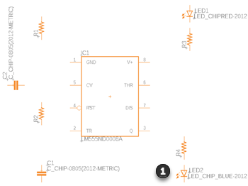
Add one LED_CHIP_BLUE_ LED to the schematic.
Scroll down the LED_CHIP variant list and select the BLUE-2012 component.
Double-click the row and move the pointer on the canvas.
Position the LED in the location shown in the image below.
Click Done or press Esc to exit the command.
Activity 1 summary
In this activity, you added nine components necessary for double LED flasher design.