Tutorial: Create a schematic design
The electronics design process is split into two distinct design stages, the schematic design, and printed circuit board (PCB) layout. The schematic design serves as the logical representation of an electronic circuit. It defines how all components are connected together, but not how they are physically placed on a circuit board.
In this tutorial, you work on the schematic design portion of the process and you:
- Place components.
- Manipulate components.
- Wire the schematic.
- Add power.
- Define values.
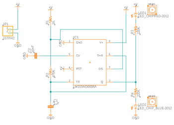
- Create a schematic of a PCB for a double LED flasher.

Schematic design of the double LED flasher circuit.
Prerequisites
- The previous Tutorial: Manage electronic component libraries is complete.