Activity 2: Moving, deleting, and rotating components
In this activity, you rearrange symbols on schematic design with rotate, move, or delete commands. Sometimes, when you add components, they might not be in the right place or orientation. This happens because you didn't know exactly where they should go. Now, you have a chance to fix the problem.
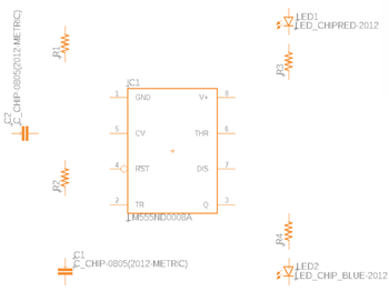
Proper location of the components in the Schematic design.
Prerequisites
- Activity 1 is complete.
Steps
Rotate objects on Schematic design.
- Click Design > Modify > Rotate
 .
. - Click the symbol origin to rotate it 90°, and continue clicking to see it rotate farther around. The origin is a small plus sign + in the center of the symbol.
- Click Done or press Esc to finish.
- Click Design > Modify > Rotate
Move objects on the Schematic design.
- Click Design > Place > Move
 , then click the symbol origin. The origin is a small plus sign + in the center of the symbol.
 - Move the symbol with your pointer.
- When the part is correctly located, click to place it.
- Click Done or press Esc to finish.
- Click Design > Place > Move
Delete objects that are not needed or were placed incorrectly.
Click the symbol origin. The origin is a small plus sign + in the center of the symbol.
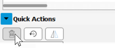
With the symbol highlighted, press Del or in the **Inspector panel > Quick Actions click Delete an object.
To restore a symbol that was accidentally deleted, click Undo
 , or press Ctrl+z.
Activity 2 summary
In this activity, you reviewed the location and orientation of the objects in the schematic design. The Rotate, Move, and Delete commands were used as necessary to position the objects as needed for the design.