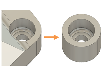
Create bolt hole preserve geometry
It is critical for the generative solution that you define where you need geometry. When you have a starting model, you can define which parts you want to preserve, and which parts the generative solution can redesign. Bolt holes that attach an object to another, are a good example of geometry that you may want to preserve.
You can use any of the tools in the Edit Model contextual environment of Generative Design, to create your preserve geometry. In this example, we sketch a circle over the bolt hole, then use Extrude ![]() with the Intersect operation, to extrude a solid feature. Intersect compares the original model with the new feature, and keeps only the geometry that the two items have in common.
with the Intersect operation, to extrude a solid feature. Intersect compares the original model with the new feature, and keeps only the geometry that the two items have in common.

Tip: Make a copy of the original model, and work with the copy, so that when the excess geometry is removed with Extrude  , you retain a copy of your starting model.
- In the Generative Design workspace, on the Define tab, click Edit Model > Edit Model
 .
. - In the Edit Model contextual environment, on the Edit Model Solid tab, click Create > Create Sketch
 .
. - Select a planar face, such as the top or bottom face, of the bolt hole.
- In the Sketch contextual tab, click Create > Center Diameter Circle
 .
. - Click in the center of the bolt hole circle to set the center of your circle sketch.
- Move your cursor outwards until you reach the required diameter and click to set the outer diameter, or type the value in the dialog.
- Right-click and select OK to finish, or Repeat Center Circle Diameter for additional bolt holes.
- Click Finish Sketch to exit sketch mode.
- Click on Body1 in the Browser, right click, and select Copy, to make a copy of your starting model.
- Click on Bodies, right click and select Save, to create Body2.
- Hide Body1 by clicking the Visible icon
 , so that subsequent operations do not affect the original model.
 - On the Edit Model Solid tab, click Create > Extrude
 .
. - Select all faces on the sketch plane that fall within the circle sketch(es).
- Rotate the model so you can see both the Extrude arrow, and the opposite plane of your geometry.
- Drag the arrow towards the opposite plane, then click on the plane to snap to it.
- Select Intersect, as the Operation in the Extrude dialog, then click OK.