Activity 2: Create preserve geometry for the bolt holes
In this activity, you create geometry to act as preserve geometry for the four bolt holes that mount the bracket into position.
In this example you use the Sketch tool to create circles, referencing the center of the existing holes and the edge of the part to define the diameter.

Prerequisites
- Activity 1 is complete.
Steps
In the Edit Model contextual environment, create circles around the four bolt holes using the Center Diameter Circle tool on the Sketch toolbar.
- On the Define tab, click Edit Model > Edit Model
 , to switch to the Edit Model contextual environment.
 - Use the ViewCube to rotate the model to expose the Bottom face.
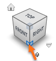
- On the Edit Model Solid tab, click Create > Create Sketch
 , then click on the bottom face of the model, to place the grid on the bottom face, and to open the sketch toolbar.
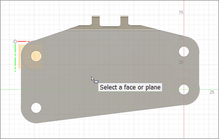
- On the Sketch tab, click Create > Center Diameter Circle
 , then click in the center of one of the bolt holes.
 - Drag your cursor to the edge of the model, and click the edge to create the circle.
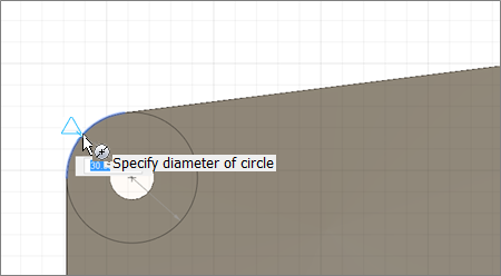
- Click the center of the next circle, followed by the edge of the model, and repeat for the remaining two circles.
- Right click the mouse to open the sketch menu, and select OK to close the tool.
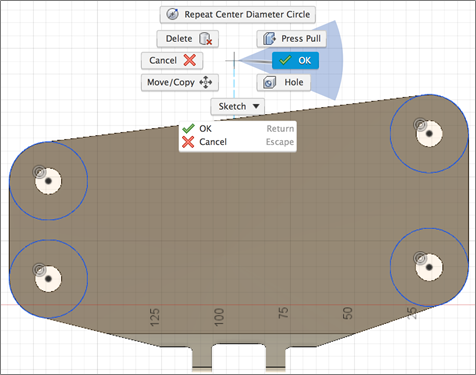
- On the Define tab, click Edit Model > Edit Model
Make a copy of the part to ensure that it is not consumed by the operation in the next step, then hide the original model body.
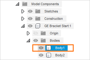
Note: In the next step you extrude the circles using an intersect operation. This extrude operation deletes the bracket except the areas that intersect the 4 extruded circles- In the Browser, click on the arrow next to (Model Components > GE Bracket > Bodies)
- Click on Body1, right click, and select Copy.
- Click on Bodies, right click and select Paste, to create Body2.
- In the Move/Copy dialog, click OK to close it.
- Hide Body1 by clicking the Visible icon
 .
.
Extrude the circles to -50mm using an intersect operation,to leave only the four areas of the bracket that intersect the profiles.
- On the Edit Model Solid tab, click Create > Extrude
 , then click the center and surrounding circles of all four bolt holes.
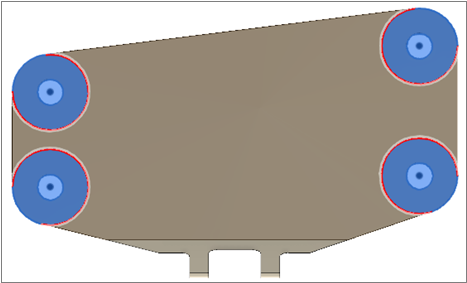
- Click the Home View to rotate the model to its original position.
- Click on the blue arrow, and drag it upwards to -50mm.
- Select the Intersect operation in the Extrude dialog.
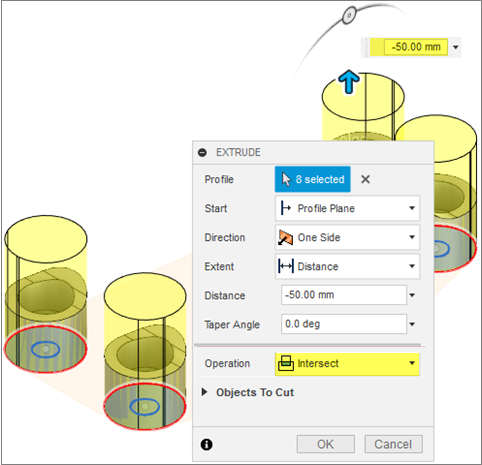
- Hover over the top outer edge of one of the preserved geometry to highlight either the edge or the top outer face, then click on it to create the four bolt hole preserve geometries.
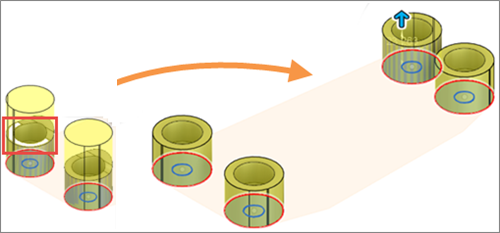
- Click OK to close the Extrude dialog.
- On the Edit Model Solid tab, click Create > Extrude
Activity 2 summary
In this activity, you created preserve geometry for the four bolt holes that mount the bracket into position.
You accomplished this task using the following tools:
- Sketch
- Center Diameter Circle
- Extrude