Symmetry plane in the Generative Design workspace
The Symmetry Plane command enables you to define a symmetry plane to generate symmetrical outcomes.
Access the command by selecting Symmetry Plane ![]() in the Design Space panel of the Generative Design toolbar.
in the Design Space panel of the Generative Design toolbar.
Select a construction plane to define it as the symmetry plane. You can define one or more symmetry planes.
Symmetry requirements
The basic requirement is that preserve and obstacle geometries need to be symmetrical about the plane(s). Additional symmetry requirements depend on the selected manufacturing methods.
| Manufacturing methods | Requirements |
|---|---|
| Unrestricted, Additive, 3-axis milling, 5-axis milling | The symmetry planes need to be orthogonal to each other. |
| 2-axis cutting, 2.5-axis milling | The symmetry planes need to be orthogonal to each other. Additionally, they need to be orthogonal or parallel to the cutting/milling direction. |
If your study setup meets the requirements then all symmetry planes are included in the design created from the outcome. It means that the design opened in the Design workspace already contains these planes. The planes are important because they are used in the T-spline creation to enforce symmetry, so that the whole body can be edited symmetrically with these planes. For example, when you modify geometry on one side of the T-Spline body, the geometry on the other side of the plane updates to match.
| Design space with a symmetry plane (Generative Design workspace) | Symmetrical outcome (Explore contextual environment) |
|---|---|
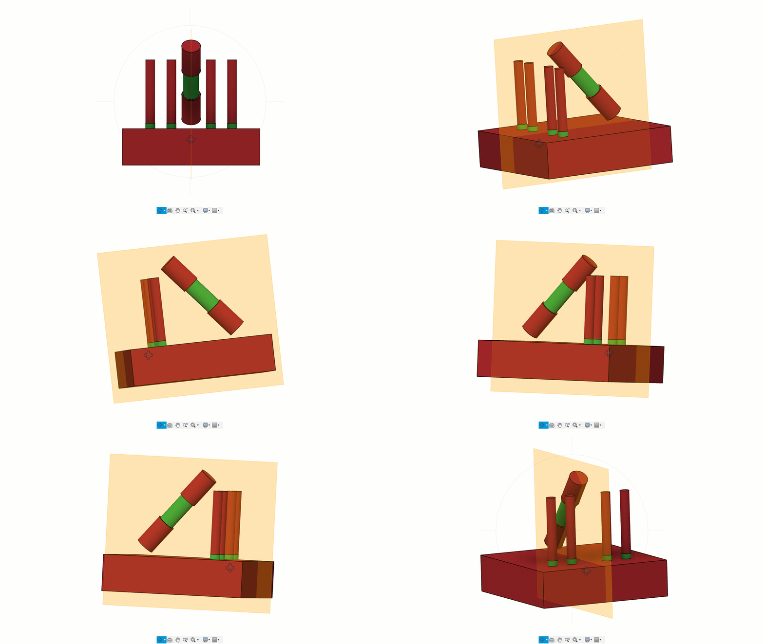 |
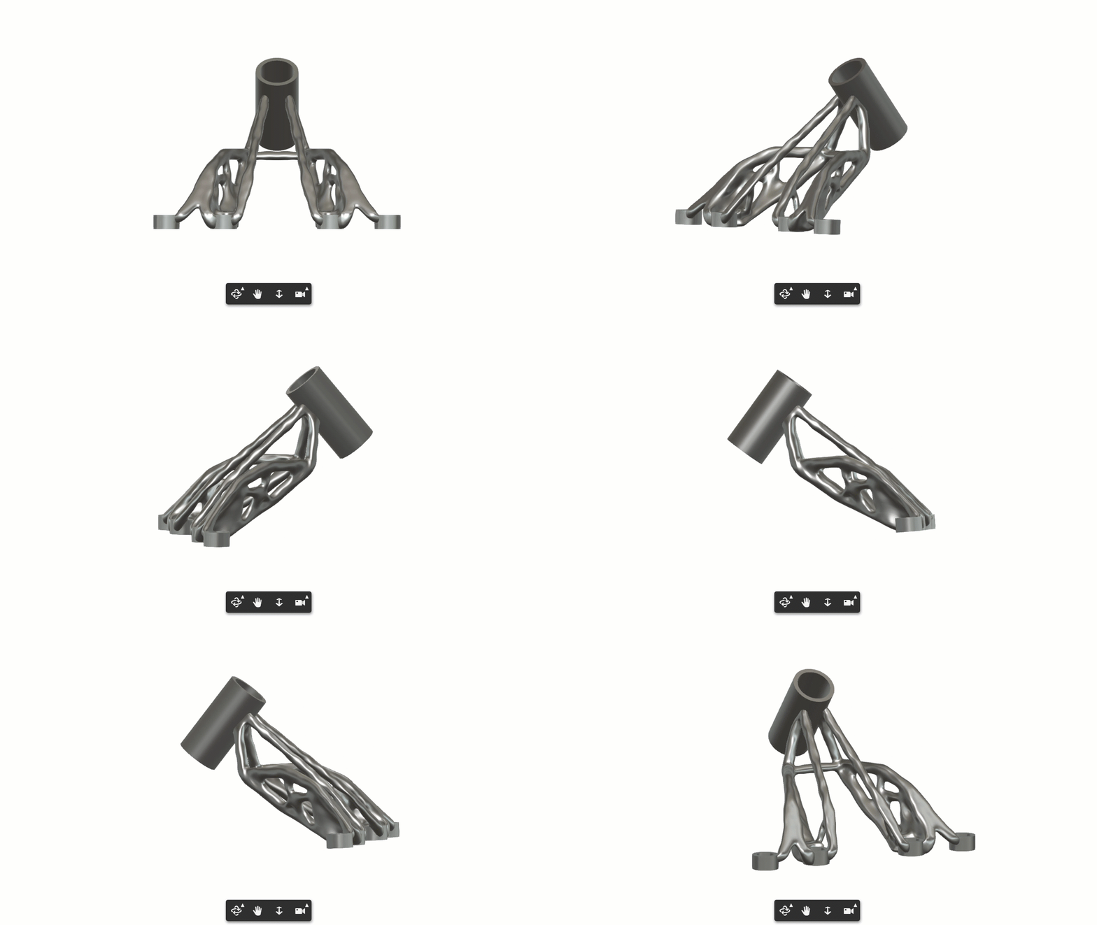 |
Examples
The following examples show three scenarios:
If you define orthogonal planes, then all symmetry planes are included in the design created from the outcome. The design opened in the Design workspace already contains these planes.
If you define orthogonal and non-orthogonal planes, then all symmetry planes are ignored during design creation. The design opened in the Design workspace doesn't contain these planes. It means that if you want to modify the T-Spline body symmetrically, you have to create these planes in the Form contextual environment again.
If you define the symmetry planes that are orthogonal or parallel to the cutting/milling direction, then all symmetry planes are included in the design created from the outcome. The design opened in the Design workspace already contains these planes.
| Example | Design space (Generative Design workspace) | Design created from outcome (Design workspace) |
|---|---|---|
| 1. Orthogonal planes | 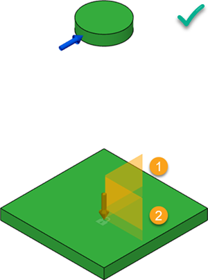 The planes 1 and 2 are orthogonal planes. |
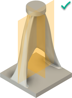 The planes are included in the design created from the outcome. |
| 2. Orthogonal and non-orthogonal planes | 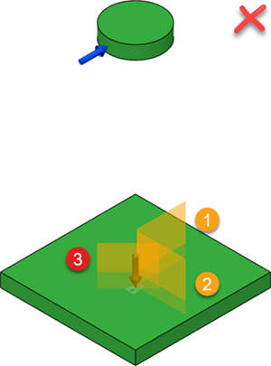 The planes 1 and 2 are orthogonal planes. The plane 3 is non-orthogonal plane. |
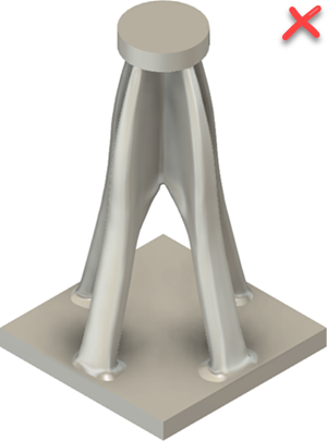 The planes are ignored during design creation. |
| 3. Orthogonal and parallel to the cutting direction | 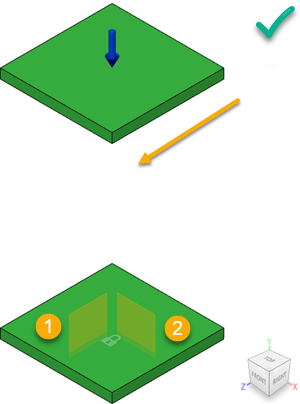 The plane 1 is parallel and plane 2 is orthogonal to the cutting direction (Z-axis). |
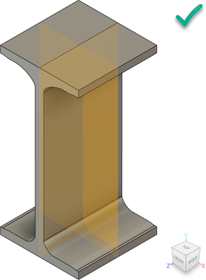 The planes are included in the design created from the outcome. |