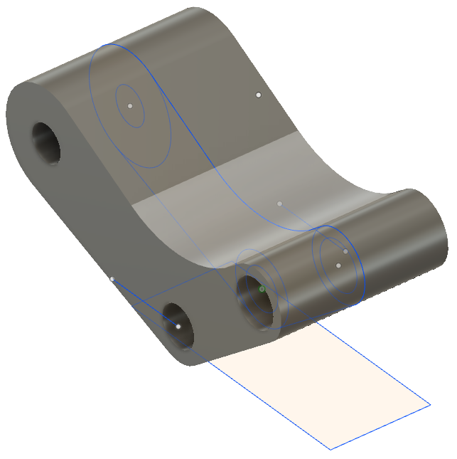
Activity 1: Create the rocker arm shape
In this activity, you open the rocker arm sketches and create the rocker arm geometry based on those existing sketches.
Prerequisites
- Fusion is started.
- Data file location: Samples > Basic Training > 04 - Modeling > 04_Model_from_sketch.f3d.
Steps
Open the rocker arm sketch.
If necessary, click Show Data Panel
 . The Data Panel appears at the left side of the program window.
In the Data Panel, under Samples, open Basic Training > 04 - Modeling > 04_Model_from_sketch.f3d.
Note: When you open a sample design in Fusion for the first time, it appears in the Model workspace.
Because the design is read-only, you should save a copy of it to a personal project.
- Click File
 > Save As.
 - In the Name box, make sure the name is My_04_Model_from_sketch.
- To the right of the Location box, click the Down Arrow icon
 .
. - Click New Project.
- In the box, type My Model Tutorials, and press Enter.
- To make My Model Tutorials the current file saving location, in the Project list, click My Model Tutorials.
- Click Save.
- Click File
From the Solid tab, select the sketch profiles of the rocker arm sketch to create a solid body.
To select the profiles, hold down Shift and select the profiles shown in the image.
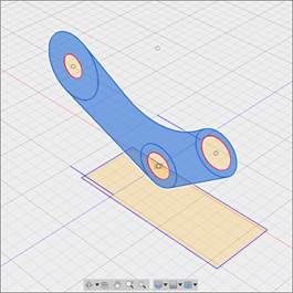
Make sure that the three center holes are the only profiles not selected.
Note: If you are having trouble selecting certain profiles, use your mouse wheel and zoom in closer; this should make selection easier.
Start the Extrude tool and define the direction to Two Sides and the Extent to To Object.
To start the Extrude tool, right click on a selected area of the sketch and select Extrude.
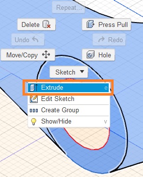
To define the extrude options in the Extrude dialog, set the Direction to Two Sides and set both Extents to To Object.
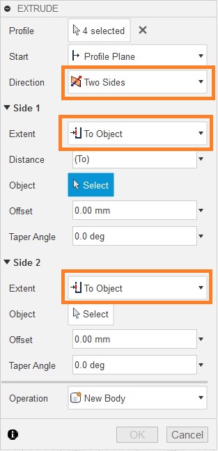 Note: You should now see two arrows appear on your selected sketch profiles. You use these arrows to define where the extrusion goes. This is especially useful when you have set geometry you can use as reference, much like our sketch here.
Define the extrusion distances to be the end points on the left- and right-side line sketches.
To set the distance for the left side extrusion, on the Extrude dialog, click Select next to the Object label within the Side 1 section.
Hover over the line sketch on the left side and click on the end point as the extent you want to extrude to.
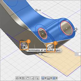 Note: When Extrude extent is set to To, make sure you select the line sketch and not the rectangle sketch. When you've done this, the extrusion automatically terminates at that point. This selection is helpful when you have reference geometry you want to use to create new geometry.
To set the distance for the right side, click Select next to the Object label within the Side 2 section of the Extrude dialog.
To define the extent of the extrusion, hover over the line sketch on the right side and click on the end point.
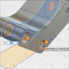
To finish the tool, click OK (or press the Enter key).
Resume sketch visibility.
To turn the visibility of the sketch back on, go to the browser.
Within the Sketches folder, ensure the visibility icon next to Sketch1 and Sketch2 are both toggled on.
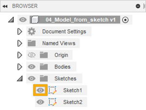 Note: The visibility of a sketch is automatically turned off after a modeling action has been committed based on that specific sketch.
Activity 1 summary
In this activity, you opened and saved the sample file to a personal folder. You selected profiles from an existing sketch, you defined the extrusion extent with an existing sketch, and then extruded the profiles into a 3D body.
