Activity 1: Create the pail box with a collapsed bottom and beveled edges
In this activity, you
- Create a box primitive on the X-Z plane
- Delete the bottom face of the box
- Extrude the sides of the box downward and scale the bottom edges inward
- Fill the hole at the bottom of the box with a collapsed face
- Bevel the top eight edges
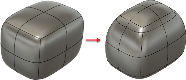
Initial box primitive (left) and the finished example with new bottom face, bottom edges scaled inward, extruded (longer) sides, and beveled top (right).
Steps
Create a box primitive on the X-Z plane using a center rectangle; its dimensions should be L: 185mm, W: 250mm, H: 185mm, each with 2 faces.
In Fusion, create a new document.
From the Fusion toolbar, click Create > Create Form.
From the Form toolbar, click Create > Box.
Mouse over the XZ plane to highlight it in the canvas.
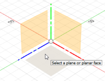
Click the XZ plane to select it as the basis for your box.
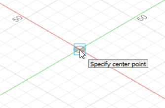
Click the center of the XZ plane to set a center point for the box.
Click another point to set the approximate size of the box.
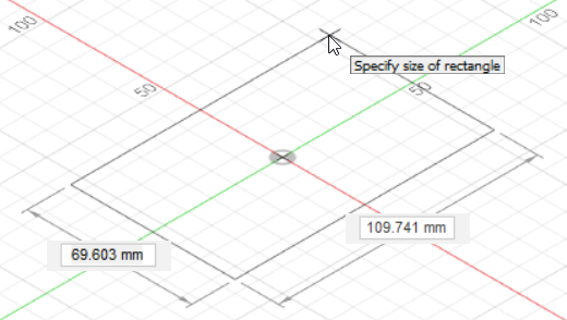
This creates a form and opens the Box dialog.
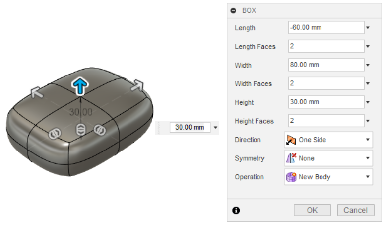
Enter these values in the Box dialog and click OK.
Length: 185mm, 2 faces
Width: 250mm, 2 faces
Height: 185mm, 2 faces
(Leave Direction, Symmetry, and Operation set to One Side, None, and New Body, respectively.)
The box is created with the dimensions you set. (You might need to adjust zoom to see the complete view.)
Delete the bottom of the box.
Click the front-right-bottom corner of the ViewCube to show the bottom of the box.
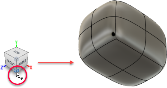
Select (Shift-click) the four bottom faces and press Delete.
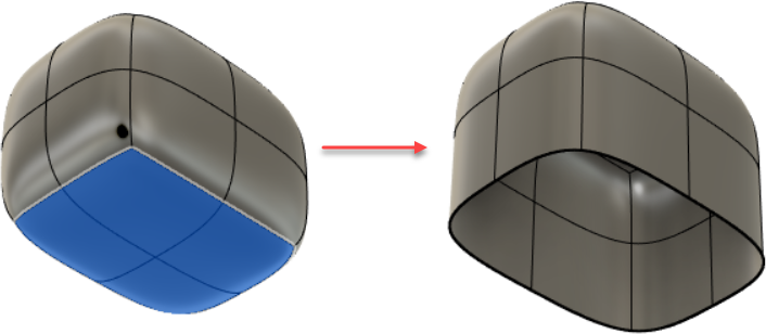
Extrude the sides of the box downward by 10mm and scale the bottom edges inward by a factor of 0.75.
From the Form toolbar, click Modify > Edit Form.
Select (Shift-click) all the bottom edges of the box.
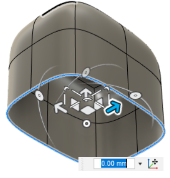
Alt-drag the vertical arrow downward to extrude the sides by 10mm.
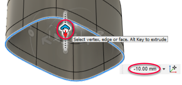 Tip: If you cannot drag exactly -10mm, enter the value in the distance box.
Drag one of the edge handles inward for a scaling factor of 0.75.

Fill the hole at the bottom of the box with a collapsed face.
From the Form toolbar, click Modify > Fill Hole.
The Fill Hole dialog displays.
Set Fill Hole Mode to Collapse.
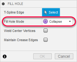
This will fill the hole by collapsing all vertices to a central point.
(Leave Weld Center Vertices and Maintain Crease Edges deselected.)
Click an edge of the opening to create the bottom face, then click OK.

Bevel the top eight edges using a bevel location of 0.5 and 1 segment.
Return to the Home view.
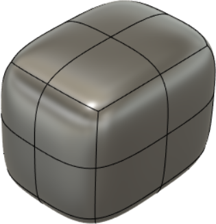
From the Form toolbar, click Modify > Bevel Edge.
With T-Spline Edge set to Select, click the top eight edges on the box.
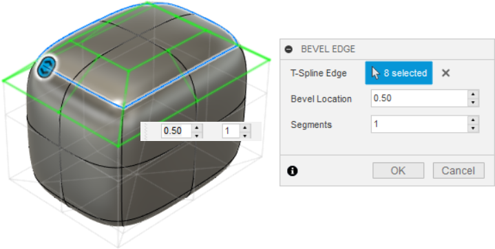
Set Bevel Location to 0.5, and Segments to 1, then click OK.
This creates eight new faces underneath the original edges you selected
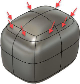
Bevel Location is the portion of the neighboring faces, as a fraction, across which the bevel spans. In this tutorial, you can see that the bevel spans half (0.5) of the top face and half of the lower face, with the new segment inserted in between.
Segments determines how many segments are created between adjacent faces.
From the Form toolbar, click Modify > Edit Form.
Shift-click the eight new faces.
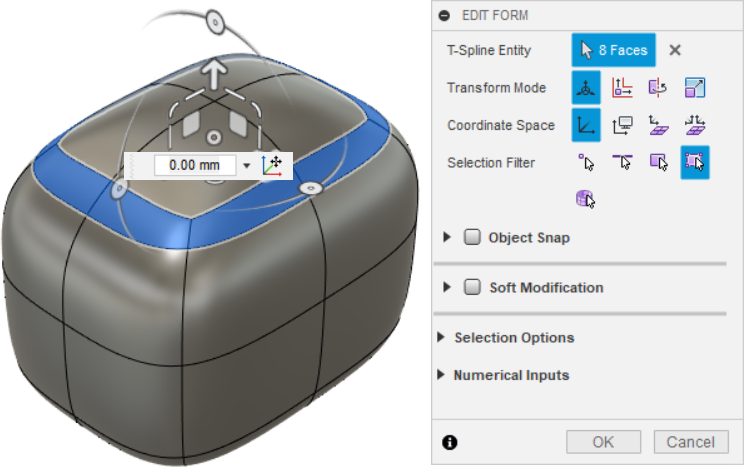
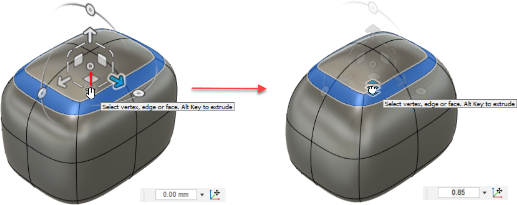
Drag the foremost corner of the manipulator inward and set the value to 0.85.
This creates a slightly more conic top surface.
Save your work.
Activity 1 summary
In this activity, you
- Created a box primitive on the X-Z plane
- Deleted the bottom face of the box
- Extruded the sides of the box downward and scale the bottom edges inward
- Filled the hole at the bottom of the box with a collapsed face
- Beveled the top eight edges

Initial box primitive (left) and the finished example with new bottom face, bottom edges scaled inward, extruded (longer) sides, and beveled top (right).