Activity 2: Apply constraints and loads
In this activity, you assume that the floor is rigid and slick. The legs can slide on the floor but are held in the Y direction. To keep the table from moving infinitely you lock the bottom of one of the legs. The single point being locked enables the other legs to translate while preventing the table from moving infinitely across the floor. To complete the study setup, you
Apply a different constraint to the bottom of each of the four legs
Apply a load on the top of the table
Use the automatic contact generator to create bonded contacts.

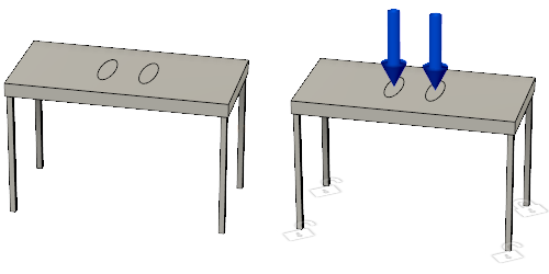
Plastic table with no constraints or loads (left) and Plastic table with constraints and loads (right).
Prerequisites
- Activity 1 is complete.
Steps
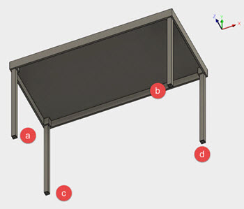
Constrain the legs in the following manner:

 - Fixed in Uy.
 - Fixed in Ux and Uy.
 - Fixed in Uy and Uz.
 - Fixed in all directions Ux, Uy, and Uz.
- Click
 (Simulation workspace > Setup tab > Constraints panel > Structural Constraints), to open the Structural Constraints dialog.
 - Click the Bottom face of the ViewCube, or rotate the model so that the feet on the bottom of the legs are visible.
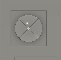
- Select the point on the bottom of leg (a) that would contact the floor. Notice that a lock appears at that point.
- In the Structural Constraints dialog, click the Ux Axis and the Uz axis to deselect them.
Note: This leaves Uy as the only constrained axis on leg (a). - Click OK to accept the constraint and close the dialog.
- Repeat the steps for table legs b, c, and d, using the constraints listed above.

Note: Unlocked padlocks are shown on three vertices, indicating that they are only partially restricted and can move along the floor.
- Click
Apply a 200 lbforce load to the top of the table, to check if it can support a 200lb person.
Note: To perform a structural buckling analysis a load compressing an element is required.- Rotate the model to see the top of the table by selecting the Top of the cube or by using the mouse.
- Click
 (Simulation workspace > Setup tab > Loads panel > Structural Loads), to open the Structural Loads dialog.
 - Use the drop-down menu to ensure that the Type is set to
 Force.
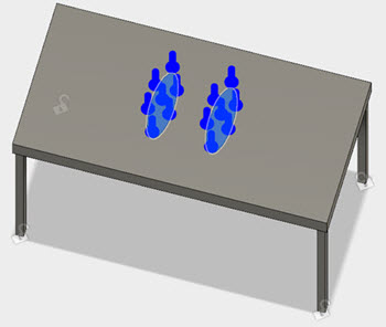
 - Select the two footprints on top of the table.
- Verify that the vector arrows indicate that the force compresses the table.

- In the Structural Loads dialog, enter 200 for the Magnitude.
- Click OK to accept the change and close the dialog.
Tip: To easily find the force required to cause buckling, use a value of 1 for the magnitude. The Buckling Load Factor is then the Critical Buckling Force.Define the contacts between the bodies that makeup the model.
Note: The legs are coincident to the table, so you can use the automatic contact generator to create bonded contacts.- Click
 (Simulation workspace > Setup tab > Contacts panel > Automatic Contacts), to open the Automatic Contacts dialog.
The parts are all coincident so the default tolerance, 0.004 in, is acceptable. - In the Automatic Contacts dialog, click Generate to generate the contacts.
- Click
Activity 2 summary
In this activity, you assumed a rigid, slick floor. To complete an appropriate analysis setup, you
- Applied a different constraint to the bottom of each of the four legs
- Applied a load to the top of the table
- Used the automatic contact generator to create bonded contacts.