Activity 1: Create a new static stress study
In this activity, you create Study 1 - Static Stress in which you
- Define the mesh size
- Select the desired units system
- Check that the model materials are properly assigned. By default, the simulation study material is the same as the material defined in the Design workspace.

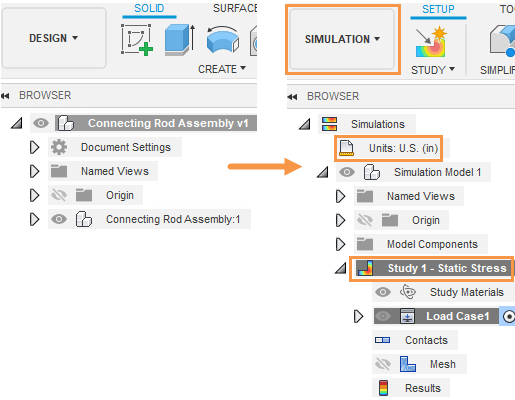
Browser when model is first imported (left). Browser after creating a new static stress study (right).
Prerequisites
- Fusion is started.
- Data file location: Samples > Basic Training > 11-Simulation > Connecting Rod Assembly.
Steps
Open the starting shape model, Connecting Rod Assembly in the Z up direction, from the Basic Training folder in the Data Panel.
- If the Data Panel is not currently shown, click
 Show Data Panel at the top of the screen.
 - The top level (home view) of the Data Panel is divided into two subsections: ALL PROJECTS and SAMPLES. Scroll down until you reach SAMPLES.
- Double-click the Basic Training folder to open it.
- Double-click the 11 - Simulation folder to open it.
- Double-click the Connecting Rod Assembly model to open it in the canvas.
Note: The sample model is read-only, so you must save a copy of it to a personal project- If the Data Panel is not currently shown, click
Identify a personal project in which to save the starting shape models.
- Click
 File > Save as.
 - Enter a name, such as Connecting Rod Assembly, in the name field.
- Expand the arrow button next to the Location field.
- Locate and click on an existing project, or click New Project to start a new project.
- Click
Identify or create a folder in which to save the starting shape models.
- Double-click on a folder in the project to select it, or create a new folder.
- To create a new folder, click New Folder.
- Type a name, such as Connecting Rod Assembly for the folder.
- Press Enter.
- Double-click the folder to make it the current file saving location.
- Click Save.
Select Static Stress as the new simulation study.
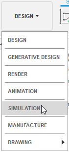
- Click on the Change Workspace drop-down menu at the top left end of the toolbar and select Simulation.

- In the New Studies dialog box, select
 Static Stress.
- Click on the Change Workspace drop-down menu at the top left end of the toolbar and select Simulation.
Set the mesh size to 0.1 in.
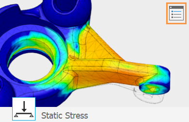
- In the upper right corner of the large thumbnail image, click the
 Settings icon to access the Settings dialog.
The General settings appear initially. - Ensure that Remove rigid body modes is NOT activated.
This option is applicable only to unconstrained models. In this study, you apply constraints. - Select Mesh from the left frame of the dialog to display the mesh settings.
- Click Absolute Size and type 0.1 in in the input field.
- Click Back to apply the changes.
- In the New Study dialog, click Create Study to create the study and close the dialog.
- In the upper right corner of the large thumbnail image, click the
Change the default units system to U.S. (in).
- In the Browser, hover over
 Units then click
  Edit.
Edit. - In the Units Settings dialog, choose U.S. (in) from the Default Unit Set drop-down list.
- Click OK to accept the change and close the dialog.
- In the Browser, hover over
Verify that the connecting rod material is Aluminum 5052 H32, and the large and small pins are Steel AISI 1020 107 HR.
- Click
 (Simulation workspace > Setup tab > Materials panel > Study Materials) to open the Study Materials dialog.
 - In the Study Materials dialog, verify that the values in the Study Material column are defined as follows:
- Connecting Rod: (Same as Model) or Aluminum 5052 H32.
- Large Pin and Small Pin (Same as Model) or Steel AISI 1020 107 HR.
- Click OK to close the Study Materials dialog.
- Click
Activity 1 summary
In this activity, you switched to the Simulation workspace to create a Static Stress study, and then you defined its parameters. You
- Defined the mesh size
- Selected the desired units system
- Checked that the model materials were properly assigned.