Activity 2: Use constraints to stabilize the model statically
In this activity, you apply all constraints needed to make the model statically stable, while not impeding the expected deformation. In general, a static stress analysis model needs to be statically stable in all three global directions.
You constrain
- The small pin, fully, in the X-,Y-, and Z- directions
- The large pin in the in the Z-direction, to prevent it from rotating in its hole
- The large pin in the Y-direction, to prevent it from moving axially
- The connecting rod along an XZ plane of symmetry, to prevent rigid-body motion in the y-direction.
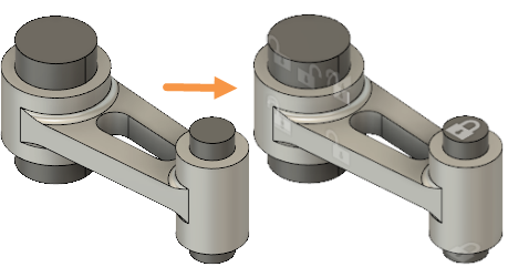
Connecting Rod assembly: before applying constraints (left) and with constraints applied (right).
Prerequisites
- Activity 1 is complete.
Steps
Fully fix the end faces of the small pin.
- Click
 (Simulation workspace > Setup tab > Constraints panel > Structural Constraints) to open the Structural Constraints dialog.
 - In the Structural Constraints dialog, confirm that Type is Fixed and Ux, Uy, and Uz Axis are all selected, in order to constrain all three directions.
- Click the top face of the small pin to select it as a Target.
Notice that the face turns blue to show it has been selected, and a white lock appears to show it has been constrained. - Rotate the model so you can see the underside of the small pin, then click on the bottom face to select it.
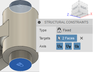
- Click OK to apply the constraints and close the dialog.
- Click
Constrain the large pin in the Z-direction using the two straight edges that run along its length.
Note: The cylindrical face of the large pin has been split to provide edges for applying constraints. These edges lie in the XY symmetry plane of the connecting rod assembly. No displacement occurs in the direction normal to the symmetry plane (in this case, the Z direction). Therefore, the natural deformation of this part is not impeded under load, by applying a Z constraint anywhere along an XY plane of symmetry.- In the Browser, expand
 Model Components and then expand
  Connecting Rod Assembly.
 - Click
 next to the
  Connecting Rod component, to hide the connecting rod.
 - Right-click in the canvas and choose
 Repeat Structural Constraints from the marking menu.
 - In the Structural Constraints dialog, click on Ux and Uy to deactivate them, leaving only Uz as a constrained Axis.
- Click the two visible straight edges on the large pin to select them, then rotate the model and select the two on the other side. If you accidentally select a face, click it again to deselect it.
Note: Each edge runs half the length of the pin, so you need to select 4 Targets, in total.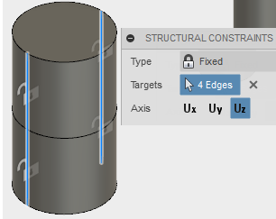
- Click OK to apply the constraints and close the dialog.
- In the Browser, expand
Constrain the large pin in the Y-direction using the circular edge around the middle of its length.
Note: The circular edge lies in the XZ plane of symmetry. The model, loads, and constraints are symmetrical about two planes: XY and XZ. Again, since this edge lies in a symmetry plane, a constraint in the normal direction does not impede the natural deflection of the part.- Right-click in the canvas and choose
 Repeat Structural Constraints from the marking menu.
 - In the Structural Constraints dialog, click on Ux and Uz to deactivate them, leaving only Uy as a constrained Axis.
- Click the two half-circle edges located midway along the large pin, to select them as the Targets.
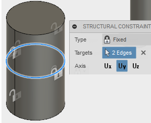
- Click OK to apply the constraints and close the dialog.
Note: The large pin is constrained in the X direction only by virtue of contact with the connecting rod. In turn, the connecting rod is only constrained in the X direction by virtue of contact with the small pin, which is fully constrained. The connecting rod and large pin must be free to move in the X direction as the pins bend and the connecting rod stretches under load.- Right-click in the canvas and choose
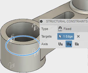
Constrain the Connecting Rod, using an edge along an XZ plane of symmetry. Again the constraint is applied where no normal (Y) translation is expected.
- In the Browser, click
 next to the
  Large Pin component, to hide the large pin.
 - Click
 next to the
  Connecting Rod component, to show the connecting rod.
 - Right-click in the canvas and choose
 Repeat Structural Constraints from the marking menu.
 - In the Structural Constraints dialog, click on Ux and Uz to deactivate them, leaving only Uy as a constrained Axis.
- Rotate the model so you can see the inside of the large hole, then click the circular edge located midway up it, to select it as the Target.
- Click OK to apply the constraints and close the dialog.
- In the Browser, click
Make the large pin visible again.
- In the Browser, click
 next to the
  Large Pin component, to make the large pin visible.
- In the Browser, click
Activity 2 summary
In this activity, you applied all constraints needed to make the model statically stable, while not impeding the expected deformation. You constrained
- The small pin, fully, in the X-,Y-, and Z- directions
- The large pin in the in the Z-direction, to prevent it from rotating in its hole
- The large pin in the Y-direction, to prevent it from moving axially
- The connecting rod along an XZ plane of symmetry, to prevent rigid-body motion in the y-direction.