Tutorial: Static stress analysis
This tutorial compares two different approaches for determining stresses and displacements in a connecting rod assembly, so you can see how the Remove rigid body modes option stabilizes a model. The separation contact is defined between all contacting faces, so they can slide freely along each other and separate, but not penetrate each other.
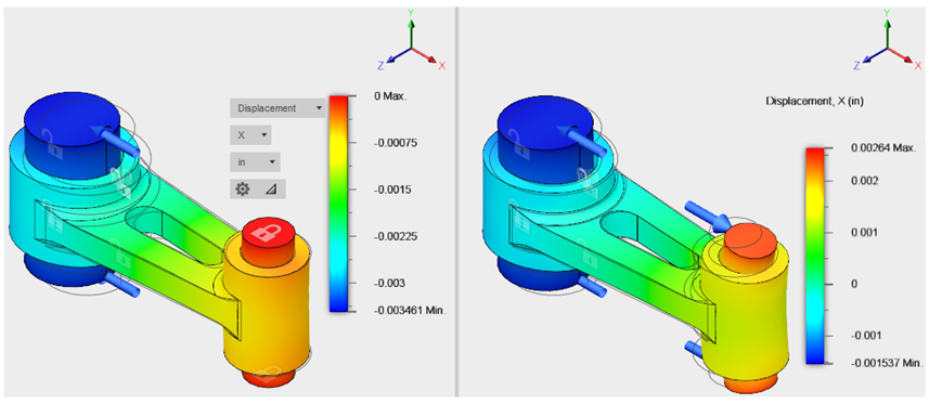
Study 1: The model is constrained in the traditional manner (statically stable). The small pin is fixed at its end faces, and the load is applied to the end faces of the large pin. Additional constraints are added to prevent Y and Z motion of the connecting rod and large pin without inhibiting their deflection under load.
Study 2: The model is partially unconstrained. The small pin is unconstrained but the other two parts are constrained in the same way as they are for Study 1. There is no X constraint anywhere on the assembly. Opposing (balanced) forces are applied to the end faces of the large and small pins. The Remove rigid body modes option is used to stabilize the model.
In this tutorial, you
- Create a new static stress analysis and define its parameters
- Apply all the constraints needed to make the model statically stable
- Apply a load, and define contact sets, and run the analysis
- Clone Study 1 to make Study 2
- Alter the constraints and loads in Study 2
- Run the analysis for Study 2 and compare the results with Study 1.

Study 1: Displacement in a statically stable model (left), and Study 2: Displacement in a partially unconstrained model (right).
In this Study 2, the small pin behaves like a simply supported beam. The end faces are free to rotate about the Z axis as the pin bends under load. The Remove rigid body modes option stabilizes the model, allowing the solution to run without constraints and preventing free-body motion of the parts.