Activity 5: Perform a Static Stress study
The objective of the shape optimization study was to reduce the weight of the part to approximately 40% of the original weight and to maximize the stiffness. A stress analysis is required to verify that the stress and displacement of the modified part shape are acceptable. Recall that the generated shape must have a safety factor of at least 2.0.
In this activity you
- Create a Static Stress study
- Run the analysis
- Review the Safety Factor result to verify that the modified part meets the design requirement.

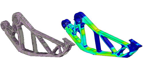
New Gripper arm model (left) and static stress analysis results on new model (right).
Prerequisites
- Activity 4 is complete.
Steps
Clone Study 1 - Shape Optimization and change the new study to a static stress one.
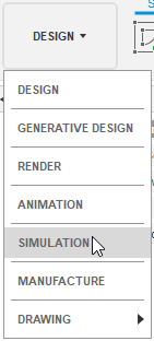
- Click on the Change Workspace drop-down menu at the top left end of the toolbar and select Simulation.
Notice that the Mesh and Results are no longer current, since you changed the design model, which is the basis for this study.

- In the Browser, right-click Study 1 - Shape Optimization and select Clone Study.
Study 2 - Shape Optimization is created and is automatically made the active study.
- Click
 (Simulation workspace > Setup tab > Manage panel > Settings), to open the Settings dialog.
 - In the Settings dialog, switch the Study Type to Static Stress.
- Click Yes, to confirm the change and close the warning.
- Click OK to close the Settings dialog and create the Static Stress study.
- Click on the Change Workspace drop-down menu at the top left end of the toolbar and select Simulation.
Solve the study.
- Click
 (Simulation workspace > Setup tab > Solve panel > Solve), to open the Solve dialog.
 - Confirm that Simulation Model 1 - Study 2 - Static Stress is selected.
- Click Solve to start the analysis and close the Solve dialog.
- When the analysis is complete, click Close to close the Job Status dialog.
- Click
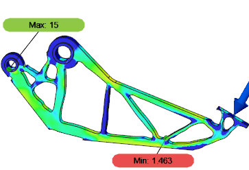
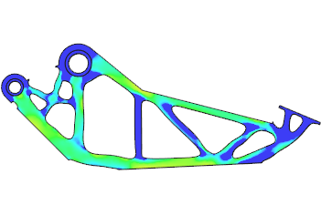
Review the results to verify that the modified part meets the design requirement. Your results will likely vary somewhat from the following image, depending on the shape of the closed splines that you sketched.
- Check the minimum Safety Factor If it is not already showing, click
 (Simulation workspace > Results tab > Inspect panel > Show Min/Max).
 - If the minimum Safety Factor is < 2, then return to the Design workspace, delete the Extrude operation from the Browser, and repeat Activity 4 from step 2.
Note: Make sure not to cut so much material this time.

- If the minimum Safety Factor is > 2, then your model meets the design requirements and can be manufactured.

- Check the minimum Safety Factor If it is not already showing, click
Activity 5 summary
In this activity, you
- Created a Static Stress study
- Ran the analysis
- Reviewed the Safety Factor result to verify that the modified part meets the design requirement.