Activity 4: Promote mesh & modify original geometry
In this activity you use the mesh object as a template for making modifications to the original geometry in the Design workspace. You
- Export the mesh to the Design workspace
- Create closed sketch objects around the material to be removed, using the Sketch environment
- Remove the enclosed sketch areas to leave only the required geometry
- Run a Static Stress analysis to check that the new design can support the applied loads.
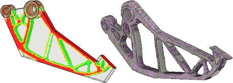
Gripper arm shape optimization result (left) and Gripper arm design model following optimization (right).
Prerequisites
- Activity 3 is complete.
Steps
Export the model to the Design workspace.
- Click
 (Simulation workspace > Results tab > Result Tools panel > Promote) to open the Promote dialog.
 - In the Promote dialog, change the Add mesh object to: selection to Model Workspace.
Note: You select this option because you want to modify the original model geometry, not the simulation model.
- Click OK to export the mesh object and close the dialog.
Notice that you are switched to the Design workspace, automatically, and the mesh object is superimposed on the original model design.
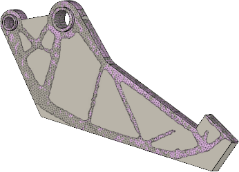
- Click
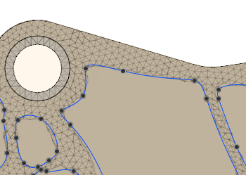
Access the Sketch environment, and create closed sketch objects around the material to be removed, by drawing splines point-to-point. Make sure to extend mesh sections that end abruptly.
Tip: You do not need to follow the meshed body contour too closely. In fact, it is advantageous to smooth out the roughness of the raw shape optimization output resulting from the irregular element shapes and locations. You could draw straight lines and arcs instead of splines to make the cutouts look more like a typical manufactured part. In this activity, we follow the meshed body fairly closely to see the stress in the raw optimized shape.
- Click
 (Design workspace > Solid tab > Create panel > Create Sketch).
 - Select the top surface of the gripper arm as the sketch plane, to open the Sketch Palette dialog.
Notice that the Sketch tab appears on the ribbon and the Sketch commands are now available.
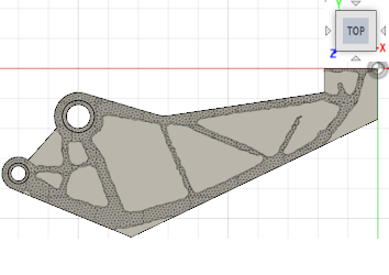
- Click
 (Design workspace > Sketch tab > Create panel > Fit Point Spline) to activate the Fit Point Spline command.
 - Using the Fit Point Spline command, click along the cutout regions drawing splines point-to-point.
Note: Click on the starting point to close the loop and start on a new closed spline.
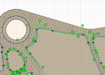
- Click (Design workspace > Sketch tab > Finish Sketch panel > Finish Sketch) after all of the closed splines have been made, to exit the Sketch environment.
- Click
Cut out the enclosed sketch areas, to leave only the required geometry.
- Click
 (Design workspace > Solid tab > Create panel > Extrude) to open the Extrude Spline.
 - In the Extrude dialog, change the Operation to
 Cut
Cut - Select all of the enclosed sketch areas by clicking inside the closed splines.
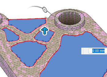
- Click and drag the extrusion direction/distance manipulator arrow down through the full thickness of the body.
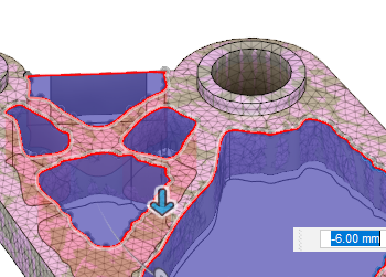
- Click OK to complete the operation, and close the Extrude dialog.
Note: If there are extra bodies left after you complete the Cut operation, select them, and delete them from the Browser.
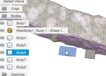
In the Browser, in the Bodies folder, you should now see only
 Body1 and the
  MeshBody1
- Click
Activity 4 summary
In this activity, you used the mesh object as a template for making modifications to the original geometry in the Design workspace. You
- Exported the mesh to the Design workspace
- Created closed sketch objects around the material to be removed, using the Sketch environment
- Removed the enclosed sketch areas to leave only the required geometry
- Ran a Static Stress analysis to check that the new design can support the applied loads.