Activity 4: Apply a prescribed translation and define contacts
In this activity you apply a 1.6 mm prescribed translation to the Top Plate, applied downwards for 1 s, to move it in the -Y direction. You then make adjustments to the study set up, to reduce the analysis time. To complete the study set up, you
Define the face on which to apply the presribed translation
Apply a prescribed translation to the Top Plate
Define the multiplier curve that controls the prescribed translation.
Define the global contacts settings to disable self-contact
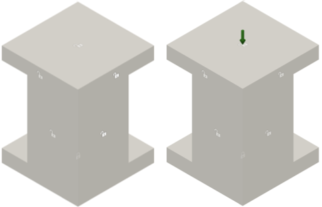
Model before applying a prescribed translation constraint (left) and with a prescribed translation constraint applied (right).
Prerequisites
- Activity 3 is complete.
Steps
Define the top face of the Top Plate as the location to apply a Prescribed Translation.
Note: In Fusion, prescribed translations are considered to be constraints rather than loads because they control the position of an object. This translation pushes the parts together.Click
 (Simulation workspace > Setup tab > Constraints panel > Prescribed Translation) to open the Prescribed Translation dialog.
Confirm that the Object Type is set to
 Faces.
Ensure that the Constraint Type is set to Displacement.
Click the top face of the Top Plate to identify it as the Selection.
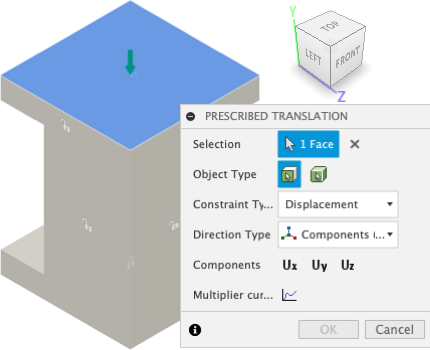
Apply a Prescribed Translation of 1.6 mm in the -Y direction to the top face of the Top Plate.
Confirm that the Direction Type is set to Components (x, y, z).
Click on the Uy Component, to select it.
Enter a value of -1.60 mm in the Magnitude Uy field.
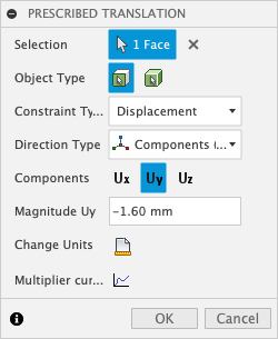
Define the Multiplier Curve that controls the prescribed translation using the values shown in the image below:
In the Prescribed Translation dialog, click
 Multiplier curve.
Enter 1 in the Multiplier column associated with the Step 1 and 0.75 in the Multiplier column in the row below. The step is incremented automatically.
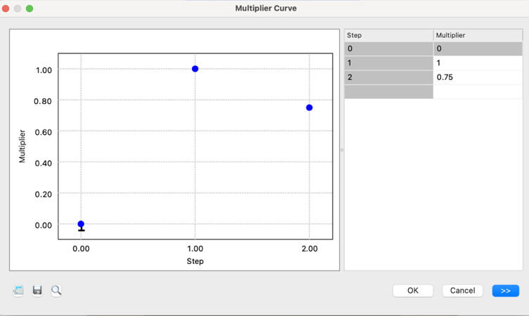 Note: This curve applies the full 1.6 mm displacement over the first step, and then backs off over the second step to 1.2 mm. You defined 10 Result Intervals per Step at the start; with 2 steps, this provides 20 result steps.
Click OK to accept the curve.
Click OK to apply the prescribed translation and close the dialog.
Automatically detect body-to-body contact pairs.
In event simulation studies contact pairs are defined between bodies, not between individual points, edges, or faces, and are detected automatically. Self-contact, where a part can deform and come into contact with a different area of itself, is supported.
Click
 (Simulation workspace > Setup tab > Contacts panel > Global Contacts), to open the Global Contacts dialog.
Confirm that Global Separation Contact is enabled and Proximity Bonded Contact is disabled.
Note: Separation contact interaction occurs wherever the two parts touch during the simulation. The parts can slide along each other and separate from each other freely, but are not permitted to penetrate each other.Expand Advanced Settings and confirm that Allow Self Contact is selected.
Click Generate to create the contact pairs and close the dialog.
Suppress self-contacts.
For this exercise, since we do not expect self-contact we can disable it to shorten the solution time.
Click
 (Simulation workspace > Setup tab > Contacts panel > Manage Contacts), to open the Event Simulation Contacts Manager dialog.
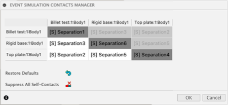 Note: There are three bodies in this model, so the matrix is 3x3. Since the relationships are symmetric, the cells in the upper half of the matrix cannot be selected.
Click
 Suppress ALL Self-Contacts
Notice that a line is drawn through each of the diagonal contacts that represent self-contact.
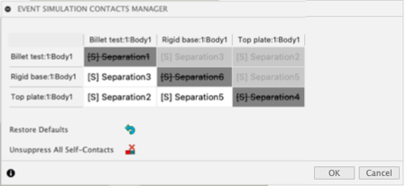
Click on each of the remaining three cells, to highlight in the canvas the bodies that each contact represents.
Click OK to close the Event Simulation Contacts Manager dialog, and suppress the selected contact pairs.
Activity 4 summary
In this activity, you
- Defined the face on which to apply the presribed translation
- Applied a prescribed translation to the Top Plate
- Defined the multiplier curve that controls the prescribed translation
- Defined the global contacts settings to disable self-contact.