Activity 2: Make the stationary body rigid and select a material
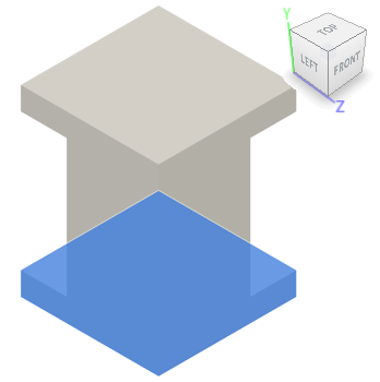
In this activity, you define the stationary base plate as a Rigid Body and select a different material for the analysis. We are not concerned with the stresses in the base. The critical stresses are at the locking fingers of the male part. Rigid parts can translate or rotate, but they cannot deform, and no strains or stresses are calculated for them.
In this activity you
Define a Rigid Body to reduce the solution time of the simulation
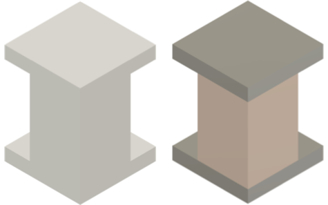
Change the material for the Simulation model to a steel for the plates, and copper for the billet.

Model before applying the materials (left) and with applied materials (right).
Prerequisites
- Activity 1 is complete.
Steps
Define the stationary base plate as a Rigid Body.
Click
 (Simulation workspace > Setup tab > Rigid Bodies panel > Rigid Bodies) to open the Rigid Bodies dialog.
Click the Rigid base plate to select it as the Target.

Click OK to accept the selection and close the Rigid Bodies dialog.
Select Copper - High Strength Alloy as the material for the copper billet in the Simulation model.
- Click
 (Simulation workspace > Setup tab > Materials panel > Study Materials) to open the Study Materials dialog.
 - Confirm that the Fusion Nonlinear Material Library is selected as the Material Library.
- Click in the Study Materials column of the first row to select the billet.
- In the Study Materials column, click
 then select Copper - High Strength Alloy from the list of materials.
- Click
Select Steel - High Strength Structural as the material for the two plates in the Simulation model.
- Click in the Study Materials column of the second row to select the stationary base plate.
- Holding down the Shift key, click in the third row to select the top plate too.
- In the Study Materials column, click
 then select Steel - High Strength Structural from the list of materials. Notice that the material in the other row does not change. All selected rows update when you click OK
 - Click OK to accept the selection and apply it to both selected rows.
Activity 2 summary
In this activity, you
- Defined the stationary base plate as a Rigid Body to reduce the solution time of the simulation
- Changed the material for the Simulation model to Copper for the billet and Steel for the two plates.