Activity 3: Add another regulator and heat sink and solve
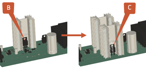
In this activity, you include another regulator and heat sink to see how they can further reduce the component temperatures to below their maximum temperature thresholds of 130 C. The regulator and heatsink are already modeled, but have been removed.
You
- Clone the second Simulation model and its study setup
- Suppress the removal of regulator C and its heat sink in the newly cloned Simulation model
- Apply 23 W power to regulator C
- Decrease the power to regulator B to 27 W.
- Apply component idealization to the new heat sink
- Change the heatsink material to Aluminum 6061
- Solve the study.

Electronics board with one heat sink (left) and with two heat sinks (right).
Prerequisites
- Activity 2 is complete.
Steps
Create a clone of the One Heatsink Simulation model and its associated study setup, and name it Two Heatsinks, so you can modify it without overwriting existing results.
- In the Setup toolbar, select
 (Simplify > Simplify) to enter the Simplify environment.
 - In the Simplify environment, in the browser, right click the One Heatsink Simulation model to open the context menu.
- In the context menu, scroll to the bottom and select Clone Simulation Model to open the Clone Simulation Model dialog.
- In the Clone Simulation Model dialog, ensure Study 1 - Electronics Cooling is selected, then click OK to create the clone.
- In the Browser, double-click the cloned Simulation model to enter edit mode, and rename it Two Heatsinks.
- In the Setup toolbar, select
Reinstate regulator C and its heatsink.
- On the Simplify timeline at the bottom of the canvas, right click the last, active, modification to open the context menu.
- In the context menu, scroll down and select Suppress Features to reinstate regulator C.
- Repeat the process with the next, rightmost active modification to reinstate the heat sink for regulator C.
- On the Simplify toolbar, click
 (Finish Simplify > Finish Simplify) to return to the Setup tab.
Apply an Internal Heat load of 23.0 W to voltage regulator C.

- On the Setup tab toolbar, select
 (Loads > Thermal Loads) to open the Thermal Loads dialog.
 - In the Thermal Loads dialog, set the Type to
 Internal Heat.
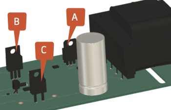
 - In the canvas, select regulator C, shown in the image, then confirm that 1 Body has been selected in the Thermal Loads dialog.
- In the Thermal Loads dialog, set the Heat Load to 23 W.
- Select OK to accept the command and close the Thermal Loads dialog.
- On the Setup tab toolbar, select
Decrease the power to regulator B to 27 W.

On the Setup tab toolbar, select
 (Manage > Load Case Attributes) to open the Load Case Atrributes dialog.
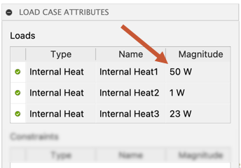
In the Load Case Attributes dialog, double-click the row with Magnitude 50 W to open the Edit Thermal Load dialog.

In the Edit Thermal Load dialog, change the Heat Load from 50 W to 27 W and press Enter on your keyboard.
In the Load Case Attributes dialog, confirm the changes are correct, then click Close to close the dialog.
Apply component idealization to the regulator C heatsink, to reduce the analysis time while maintaining solution accuracy.
- On the Setup toolbar, in the Cooling panel, select
 Heat Sink to open the Heat Sink dialog.
 - In the canvas, select the heat sink for regulator C and confirm that it is highlighted in blue.
- In the Heat Sink dialog, confirm that 1 Body is selected, then click OK to accept the change and close the dialog.
- On the Setup toolbar, in the Cooling panel, select
Change the material for the regulator C heat sink to Aluminum 6061.
- On the Setup toolbar, in the Materials panel, select
 Study Materials to open the Study Materials dialog.
 - In the canvas, select the heat sink and confirm it is highlighted in blue.
- In the Study Materials dialog, in the Study Material column, click the highlighted heatsink row twice to open the list of materials, then select Aluminum 6061 and press Enter on your keyboard.
- Click OK to accept the change and close the dialog.
- On the Setup toolbar, in the Materials panel, select
Check that the study is setup properly, then run the analysis.
On the Setup toolbar, check
 (Solve panel > Pre-check), and confirm it is green with a white check mark.
On the Setup toolbar, click
 (Solve panel > Solve), to open the Solve dialog.
In the Solve dialog, click Solve 1 Study to run the analysis and close the dialog.
Note: Meshing and solving the analysis can take several minutes.When the analysis is complete, click Close to close the Job Status dialog.
Activity 3 summary
In this activity, you
- Cloned the second Simulation model and its study setup
- Suppressed the removal of regulator C and its heat sink in the newly cloned Simulation model
- Applied 23 W power to regulator C
- Decreased the power to regulator B to 27 W.
- Applied component idealization to the new heat sink
- Changed the heatsink material to Aluminum 6061
- Confirmed the study was set up properly, then solved it.