Activity 2: Define the modeling constraints
In this activity, you define the modeling constraints to ensure that the shape optimization design meets certain design expectations.
The gripper arm is used by a robot, with one or more other arms, to grab objects. The new arm design must be able to lift and move the same weight. The arm is held in place by two pins, and this constraint needs to be accounted for during the simulation. These two areas of the arm, the bolt holes for the pins and the gripping face of the arm, need to be preserved in the new design. In addition, you want the new design to be symmtrical through the thickness, like the original design.
In this activity, you
- Use pin constraints to constrain the model for simulation purposes
- Apply a load on the gripping surface, to ensure the design can handle compressive loads
- Preserve material around both the bolt holes, to ensure that the pins can function as expected.
- Create a symmetry plane through the thickness so that the new design is symmetrical through the thickness like the original design.
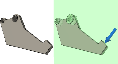
Gripper arm before applying modeling constraints (left) and with modeling constraints applied (right).
Prerequisites
- Activity 1 is complete.
Steps
Apply Pin constraints to the inside surface of each of the bolt holes, in the Radial and Axial directions.
- Click
 (Simulation workspace > Setup tab > Constraints panel > Structural Constraints) to open the Structural Constraints dialog.
 - Set the Type to
 Pin.
Pin. - Select the inside surface of each of the two bolt holes, as the two Target Faces.
- Confirm that the
 Radial and
  Axial directions are selected.
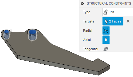
- Click OK to accept the commands and close the Structural Constraints dialog.
- Click
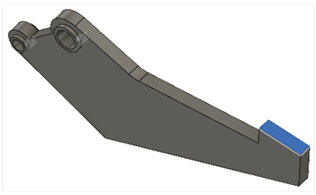
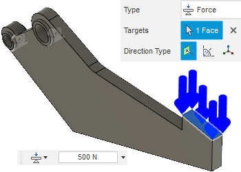
Apply a Force of 500 N, in the Normal direction, on the gripping surface. The gripper arm is used by the robot to grab objects. The shape you generate must handle compressive loads on the gripping surface.
- Click
 (Simulation workspace > Setup tab > Loads panel > Structural Loads) to open the Structural Loads dialog.
 - In the Structural Loads dialog, set the Type to
 Force, and the Direction Type to
  Normal.
 - Click on the gripping surface to select it as the Target Face.
- Enter a load of 500 N.
- Make sure the load is acting in compression (pointing toward the surface) and click OK.
- Click
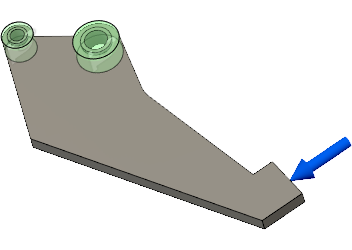
Preserve 8 mm of material around the large bolt hole, and 5.5 mm of material around the small one, so the pins can function as expected. The gripper arm is held in place by the two pins.
- Click
 (Simulation workspace > Setup tab > Shape Optimization panel > Preserve Region) to open the Preserve Region dialog.
 - If you have changed the model viewpoint since opening the model, click
 Home view above the ViewCube, to restore the default isometric view.
 - Click the inside surface of the large bolt hole to select it as the Centroid Location Face.
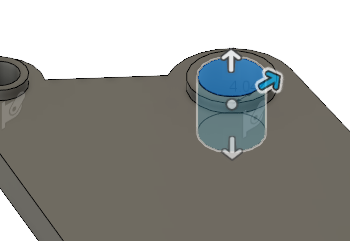
- Adjust the Radius to 8 mm.
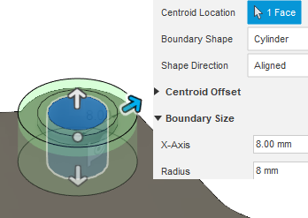
- Click OK to accept the command and close the Preserve Region dialog.
- Repeat steps a through e for the small bolt hole, adjusting the radius to 5.5 mm.
- Click
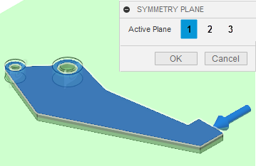
Create a symmetry plane through the thickness so that the optimized shape is symmetric through the thickness like the original gripper arm design.
- Click
 (Simulation workspace > Setup tab > Shape Optimization panel > Symmetry plane) to open the Symmetry Plane dialog.
 - Select the top surface of the gripper arm.
- Click OK to accept the command and close the Symmetry Plane dialog.
- Click
Activity 2 summary
In this activity, you
- Used pin constraints to constrain the model for simulation purposes
- Applied a load on the gripping surface, to ensure the design can handle compressive loads
- Preserved material around both the bolt holes, to ensure that the pins function as expected.
- Created a symmetry plane through the thickness so that the new design is symmetrical through the thickness like the original design.