Activity 1: Sketch the wall outlet
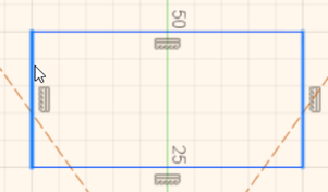
In this activity, you create the outer profile of the wall-outlet cover by sketching a rectangle. Next, you create a circle at the center of the sketch. Then, you create a construction line to use as a mirror line. Lastly, you sketch features in the upper half of the outlet by sketching a rectangle and two arcs and then mirror these objects to the bottom half.
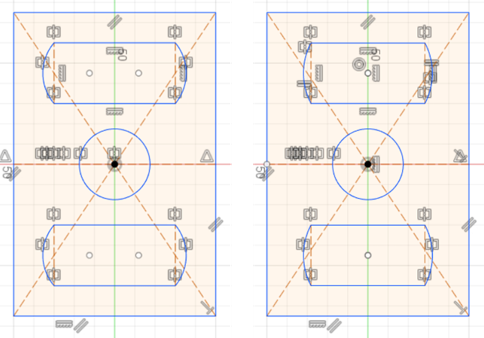
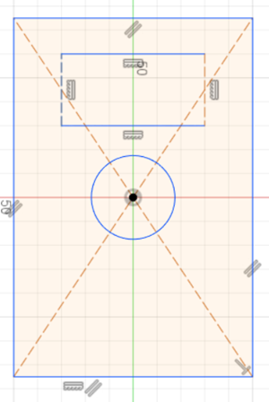
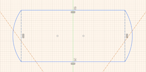
Sketch of the wall-outlet with its features.
Steps
Select the top plane to sketch on.
If necessary, enter the Design workspace by clicking the workspace switcher and selecting Design.
If necessary, open a new design. To open a new design, click File > New Design.
Click Solid tab > Create panel drop-down list > Create Sketch.
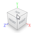
On the ViewCube, located on the top-right of the canvas, click Top.
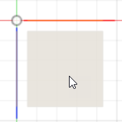
The view in the canvas orients to show you the top plane. Click the top plane to begin sketching on the top plane.
Sketch a rectangle that has the origin at its center.
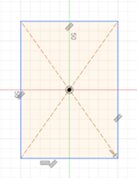
Click Create panel drop-down list > Rectangle > Center Rectangle.
Tip: If you are having trouble finding a specific tool, you can search for tools by name by pressing the S key on your keyboard. Pressing S displays the toolbox where you can search for specific tools.Click the origin
 and sketch a rectangle. Don't worry about the size of the rectangle right now, we will specify precise dimensions later on in this tutorial.
Sketch a construction line from one side of the rectangle to the other and ensure it runs through the origin.
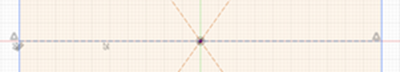
With the sketch still active, from the Create panel, click the Line tool.
Mouse over the midpoints of the rectangle's sides and sketch the line. The
 icon appears to let you know that you are on the midpoint of a line.
From the Ribbon buttons, click Select
 .
.Click the line you have just created to select it.
On the Sketch Palette, underneath Options, click Construction
 . The line turns into a construction line by changing from a solid line to a line with dashes.
Deselect the line by pressing the Esc key.
Note: You can also anywhere in the canvas to deselect the line.
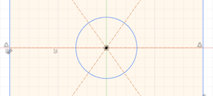
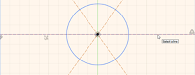
Sketch a circle with its center point on the origin.
On the Sketch tab, click Create panel drop-down list > Circle > Center Diameter Circle.
Click the origin, which should be at the midpoint of the construction line (created in Step 3) and sketch a circle.
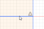
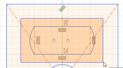
To begin creating the outlet's cutout, sketch a rectangle above the circle and turn the two vertical sides of the cutout rectangle into construction lines.
On the Sketch tab, click Create panel drop-down list > Rectangle > 2-Point Rectangle.
Sketch a rectangle above the circle.
From the Ribbon, click the Select
button.To select multiple sides of the rectangle, hold Shift and click on the vertical sides of the rectangle. The selected sides highlight with a darker color compared to the rest of the shape.
On the Sketch Palette, underneath Options, click Construction
. Both lines turn into construction lines.
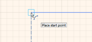
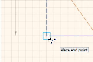
Sketch one arc on either side of the rectangle that we sketched for the cutout feature.
On the Sketch tab, click Create panel drop-down list > Arc > 3-Point Arc.
You must place three points to create your arc. Place the first point on the top-left corner of the cutout rectangle.
Place the second (end point) at the bottom-left corner of the cutout rectangle.
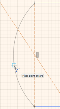
Place the third, final point as indicated in the following image. Ensure you do not place it at the center of the arc. Placing the point exactly at the center creates a constraint automatically. You can save time when you create constraints automatically, but for this tutorial, we will refrain from placing automatic constraints during sketching.
Repeat steps b, c, and d for the other side of the rectangle cutout.
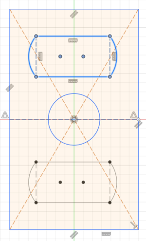
Mirror the cutout to the lower half of the outlet cover.
On the Sketch tab, click Create panel drop-down list > Mirror.
Click and hold the left mouse button to drag a selection over the rectangle and arc entities. In the Mirror dialog, there should be 12 objects highlighted.
 Note: The mirror tool may preselect some objects for you to mirror. Next to the Objects field in the Mirror dialog, you can cancel any selection by clicking X.
In the Mirror dialog, click the Select button next to the Mirror Line field to let you select a mirror line.
Select the construction line that runs through the center of the wall outlet rectangle.
The cutout appears in the lower half of the outlet as a preview. Click OK.
Activity 1 summary
In this activity, you created the outer profile of the wall-outlet cover by sketching a rectangle. Next, you created a circle at the center of the profile. Then you created a construction line to use as a mirror line. Lastly, you sketched features (the cutout) in the upper half of the outlet by sketching a rectangle and two arcs and then mirrored the objects to the bottom half.
Sketch of the wall-outlet with its features.