Activity 1: Create the basic shape
In this activity, you sketch the basic shape of the part. You create several constraints and add dimensions.
Prerequisites
- Fusion is started.
Steps
Create a new design and start the sketch.
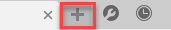
- To create a new design, click the + tab. This creates a new tab for your design.
- To open the Sketch tool, click Solid (tab) > Create > Create Sketch.

- You are now prompted to select a plane to sketch on. To do this, select the "Top" (XY) plane.
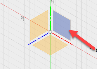
Note: Aside from the origin planes, you can create sketches on one of the three default planes, on a custom construction plane, or on an existing model face. (More on this later.)
- To create a new design, click the + tab. This creates a new tab for your design.
Sketch the basic shape.
- To start the Line tool, click Sketch > Line.

- Select the sketch origin.
- Click to end the line.
- Continue sketching lines as follows:
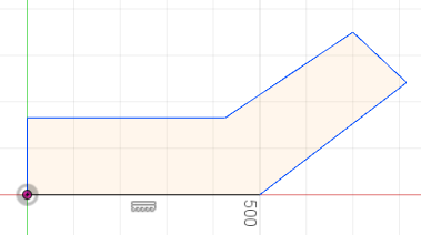
Note: As you place the lines, some constraints are automatically created. If you do not get exactly the same ones as shown, it is ok as we add constraints in the next steps. Try to make sure your first line is roughly 500 mm. It is good practice to sketch shapes close to the correct size. - To exit the tool, press keyboard Esc.
- To start the Line tool, click Sketch > Line.
Create the Perpendicular, Horizontal/Vertical, and Equal constraints.
- To constrain certain pairs of lines to be perpendicular, select the Perpendicular constraint.
 Select a pair of lines that meet at a corner as shown below. Repeat for the other two pairs that meet at corners as marked below.
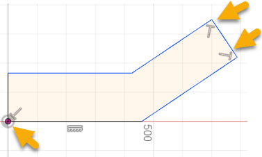
- To constrain the two lower lines to be horizontal, select the Horizontal/Vertical constraint
 . Select the two lower lines (marked below):
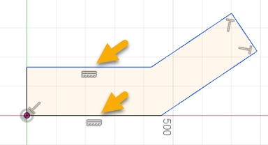
- To constrain the two equal-length pairs of lines, select the
Equal constraint. Select the two pairs as shown:
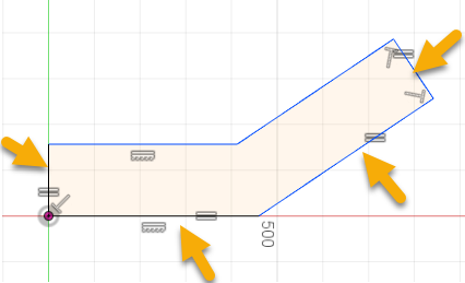
- To exit the tool, press keyboard Esc.
- To constrain certain pairs of lines to be perpendicular, select the Perpendicular constraint.
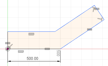
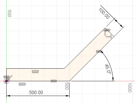
Assign dimensions to the lower line, the angle, and the upper right edge.
- To dimension the lower line, click Sketch > Dimension,
 and select the line. Click just off the line to place the dimension, and enter a value of 500 mm. Press keyboard Enter to accept the value.
- To define the angular dimension, click Sketch > Dimension, and select the bottom line and the angles line. Place the dimension, and enter 45. Press keyboard Enter to accept the value.
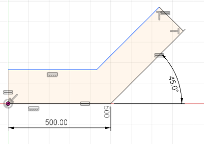
- To create an aligned dimension, click Sketch > Dimension, and select the upper right line. Move just away from the line, and enter 100.Press keyboard Enter to accept the value.
- To exit the tool, press keyboard Esc.
- To dimension the lower line, click Sketch > Dimension,
Activity 1 summary
In this activity, you sketched the basic shape of the part and added constraints and dimensions to the sketch.